Sensor isolation system

a technology of isolation system and sensor, which is applied in the direction of electrical apparatus construction details, machine supports, instruments, etc., can solve the problems of large thermal stress, adversely affecting the performance of the sensor, and the typical small size of the micro-electro-mechanical die, etc., to reduce the warping of the sensor, easy to fabricate, and inexpensive

Inactive Publication Date: 2003-02-27
CHARLES STARK DRAPER LABORATORY
View PDF6 Cites 56 Cited by
  • Summary
  • Abstract
  • Description
  • Claims
  • Application Information

AI Technical Summary

Benefits of technology

0012] It is a further object of this invention to provide such a sensor isolation system which eliminates the problems associated with attaching the sensor directly to the package.
0013] It is a further object of this invention to provide such a sensor isolation system which reduces warping of a sensor.
0014]...

Problems solved by technology

Micro-electro-mechanical (MEM) dies, such as gyroscopes and accelerometers are typically very small and sensitive to thermal and mechanical stresses.
Furthermore, any minor stresses that do occur should be stable and cannot exhibit any hysteresis effects which would affect performance of the sensor.
When the sensor is directly bonded to the package, a large thermal stress develops because the thermal expansion coefficient of the package often greatly exceeds the thermal expansion coefficient of the sensor.
The result is warping of the sensor which adversely affects its performance.
This prior art technique also makes the sensor susceptible to any externally applied forces.
Using this prior art technique, localized attachment is susceptible to alignment s...

Method used


Image

  • Sensor isolation system
  • Sensor isolation system
  • Sensor isolation system

Examples


Embodiment Construction

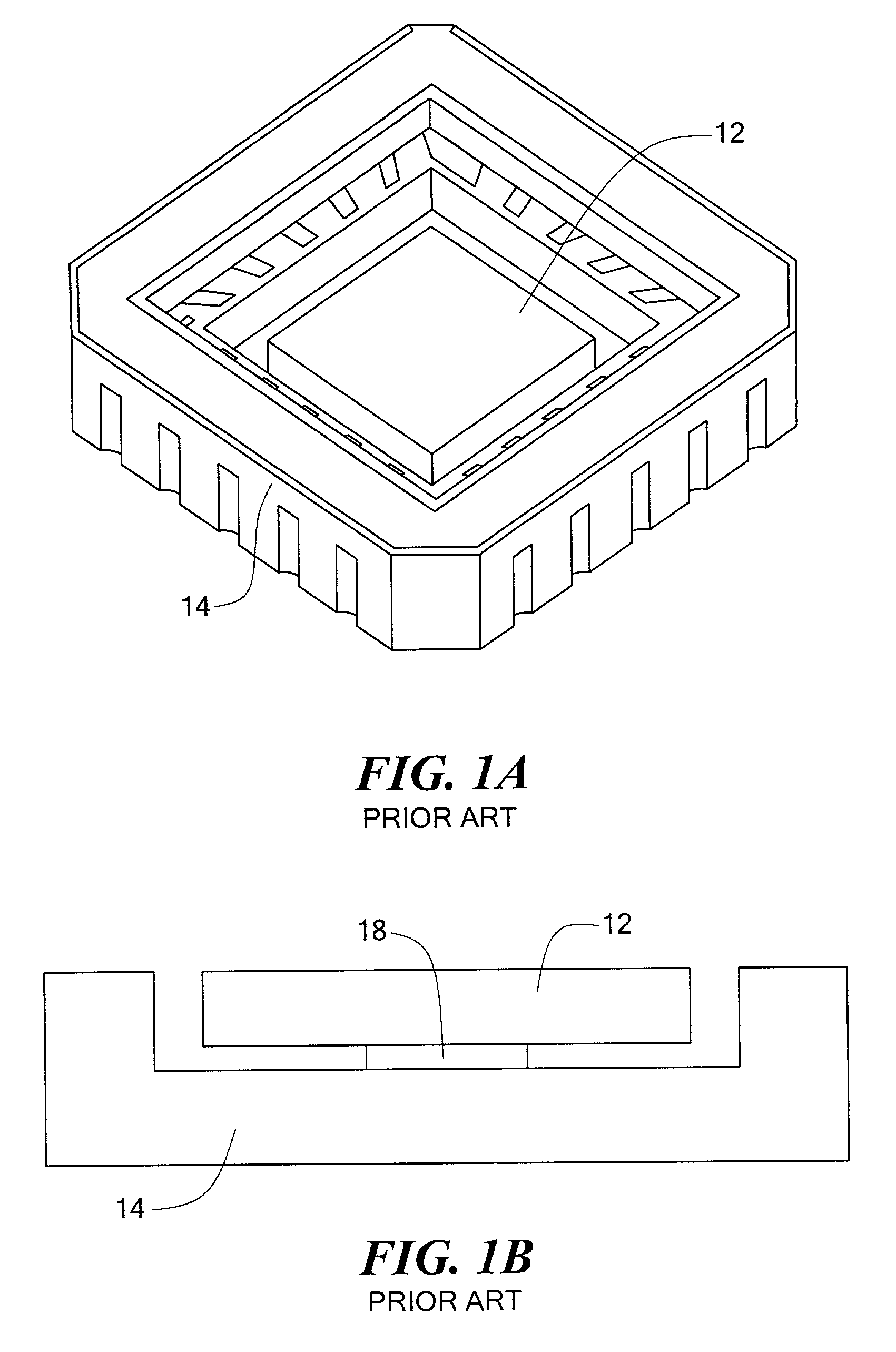
[0046] As explained in the Background Section above, sensor 12, FIG. 1 is shown mounted directly to package 14 in accordance with the prior art. Sensor 12 maybe a micro-electro-mechanical (MEM) gyroscope / accelerometer or other type of sensor. In the prior art, sensor 12 is rigidly mounted to the floor or substrate of package 14 as shown. Hermetic package 14 is typically made of aluminum oxide. Another prior art technique, as also delineated in the Background Section above, employs small pad 18, FIG. 1B which is placed near the center of package 14 in an attempt to isolate sensor 12 from thermal and mechanical stresses and strains.

[0047] However, these prior art systems exhibit several distinct disadvantages. First, the thermal expansion of package 14, typically made of aluminum oxide, is significantly greater than the thermal expansion of sensor 12. Consequently, when sensor 12 is directly bonded to package 14, large thermal stresses develop which cause sensor 12 to warp which adver...


PUM


Abstract

A sensor isolation system including a sensor, a package for the sensor, and a compliant interposer disposed between the sensor and the package and interconnecting the sensor to the package to isolate the sensor from thermal and mechanical stresses and yet at the same time providing a physical interconnect between the sensor and the package.

Description

PRIORITY CLAIM[0001] This invention claims priority of provisional patent application serial No. 60 / 313,931 filed Aug. 21, 2001.[0002] This invention relates to a sensor isolation system and also to a compliant interposer which insulates a sensor from thermal and mechanical stresses while providing a physical interconnection between the sensor and the package.[0003] Micro-electro-mechanical (MEM) dies, such as gyroscopes and accelerometers are typically very small and sensitive to thermal and mechanical stresses. In the prior art, the sensor die is rigidly mounted to the floor or substrate of a ceramic chip carrier package to maintain axis alignment, bias stability, and scale factor stability with respect to the package over time and temperature variations. The mounting scheme used strives to maintain rigidity and stability over a wide range of environmental conditions, such as temperature cycling, vibrational stresses, and g-loading. At the same time, the package should not impart ...

Claims


Application Information

Patent Timeline
IPC IPC(8): F16F1/18F16F15/073G01D11/30
CPCF16F1/18F16F15/073G01D11/30B81B7/0048
Inventor ANDERSON, RICHARD S.HANSON, DAVID S.KASPARIAN, FREDERICK J.MARINIS, THOMAS F.SOUCY, JOSEPH W.
Owner CHARLES STARK DRAPER LABORATORY
Why Eureka
Try Eureka