
Optical microfluidic devices and methods

a microfluidic device and optical technology, applied in the direction of optical radiation measurement, electrodialysis, isotope separation, etc., can solve the problems of extended time frames, large number of samples processed at high speed, and often limited progress

Inactive Publication Date: 2003-03-13
SRI INTERNATIONAL
View PDF3 Cites 88 Cited by
  • Summary
  • Abstract
  • Description
  • Claims
  • Application Information

AI Technical Summary

Benefits of technology

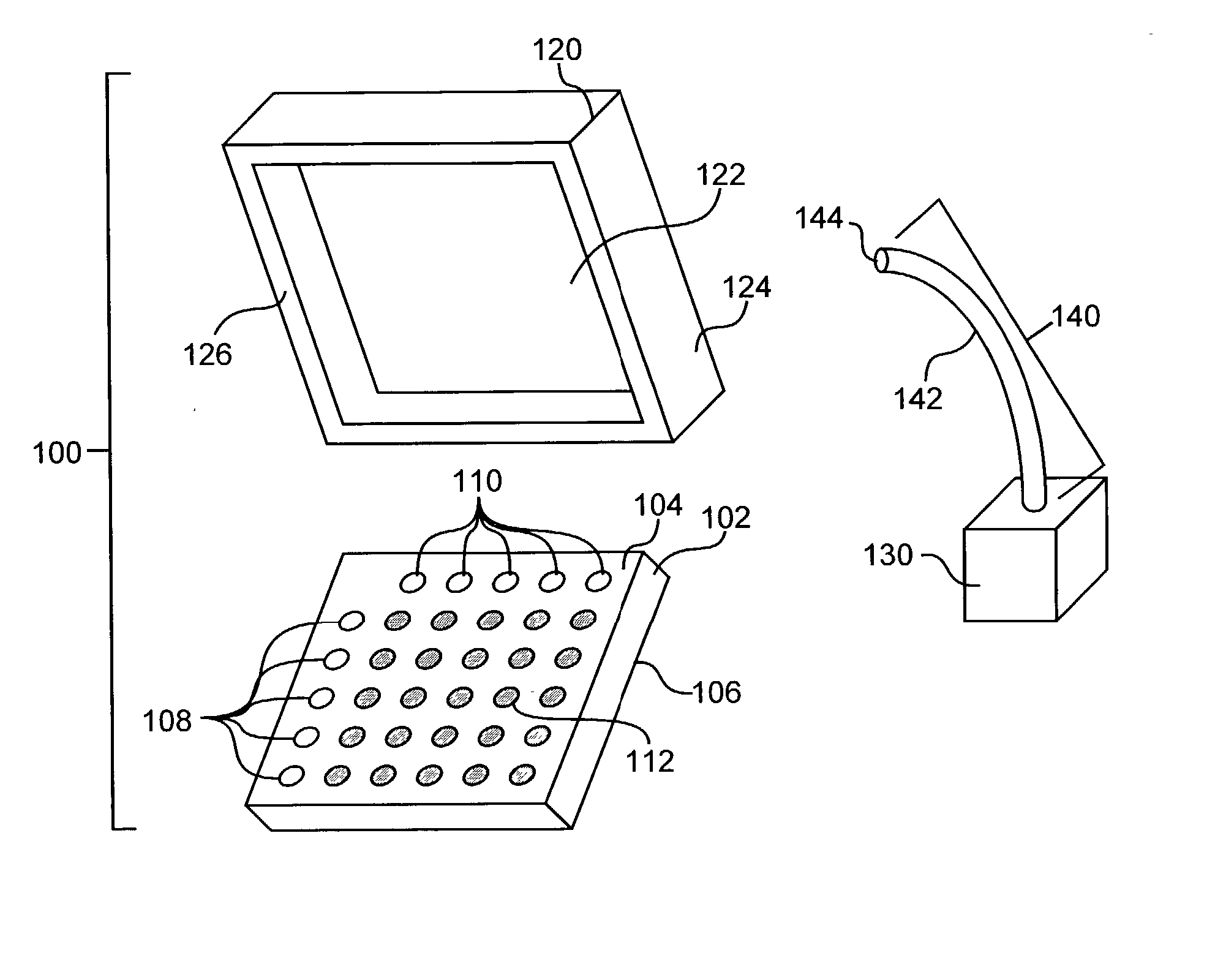
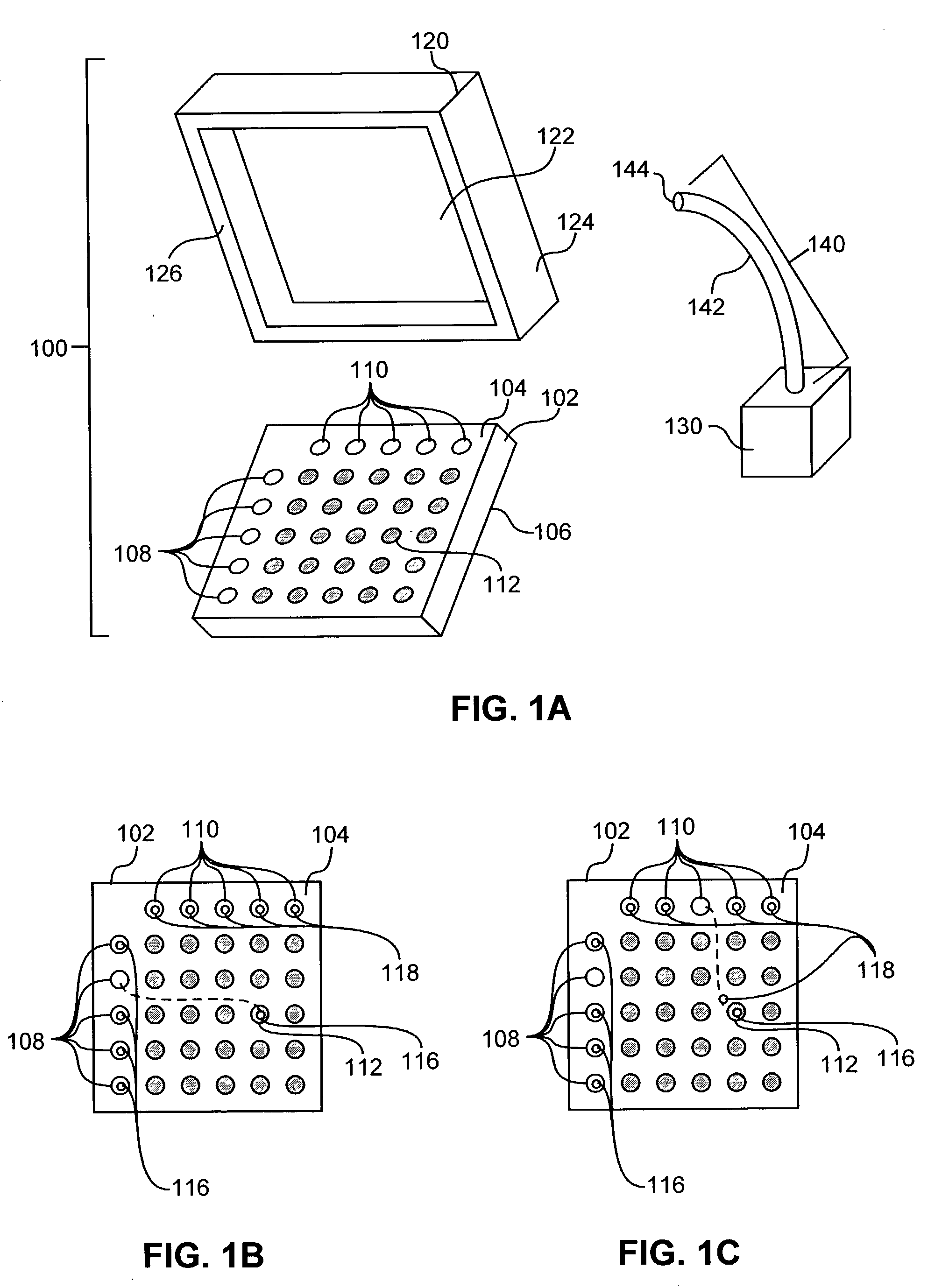
[0017] In a first embodiment, an optical microfluidic device is provided, comprising a solid substrate, an electromagnetic radiation source, and a means for directing electromagnetic radiation. The solid substrate has a fluid-transporting surface and an opposing electromagnetic radiation-receiving surface, and is comprised of a material that is substantially transparent to electromagnetic radiation of a particular wavelength. The electromagnetic radiation source serves to generate electromagnetic radiation having the particular wavelength. The means for directing electromagnetic radiation is adapted to direct radiation generated by the source toward the radiation-receiving surface of the substrate. As a result, the directed electromagnetic radiation is transmitted through the substrate to the fluid-transporting surface in a manner effective to optically move one or more droplets of a selected fluid on the fluid-transporting surface from a first site to a second site.
[0018] In another embodiment, the invention provides an optical microfluidic device as above, except that the solid substrate is not necessarily comprised of a substantially transparent material. In such a case, an optically homogeneous cover plate is provided, comprising a material that is substantially transparent to electromagnetic radiation of the particular wavelength. In addition, the cover plate has an electromagnetic radiation-receiving surface and an opposing surface that faces the fluid-transporting surface. Accordingly, the means for directing electromagnetic radiation is adapted to direct radiation generated by the source toward the radiation-receiving surface of the cover plate. The directed electromagnetic radiation is transmitted through the cover plate to the fluid-transporting surface of the substrate in a manner effective to optically move one or more droplets of a selected fluid on the fluid-transporting surface from a first site to a second site.
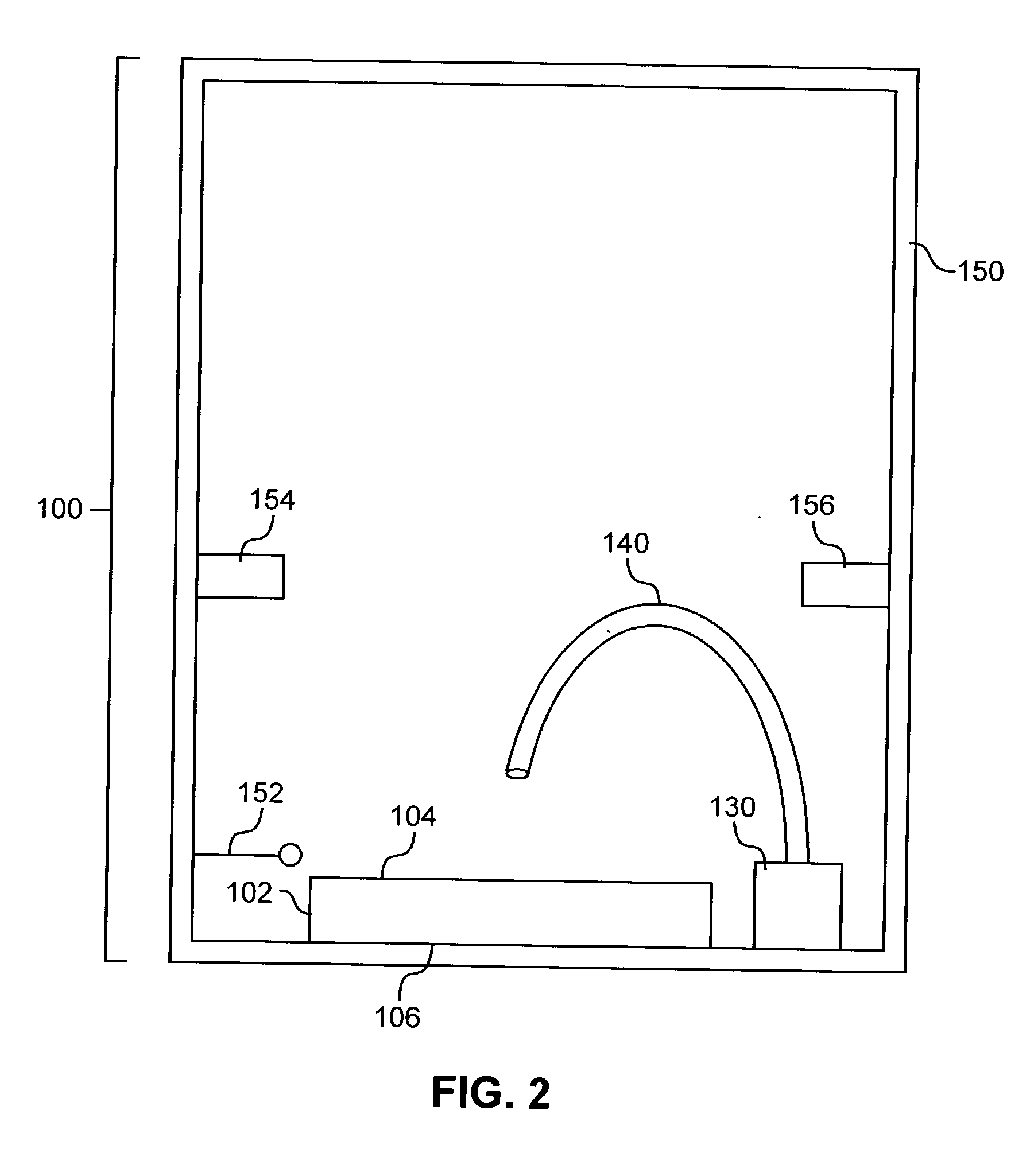
[0019] In another embodiment, the invention provides an optical microfluidic device as generally described above except that neither a substantially transparent substrate or cover plate is required. Instead, the inventive device is comprised of a substrate (transparent or opaque) having a fluid-transporting surface, an electromagnetic radiation source, and a means for reducing evaporative loss of any droplet or droplets on the fluid-transporting surface.
[0020] In yet another embodiment, a method is provided for controllably moving a droplet of a selected fluid across a surface of a solid substrate. A droplet of a selected fluid is deposited on a first site of a fluid-transporting surface of a solid substrate. The substrate is comprised of a material that is substantially transparent to electromagnetic radiation of a particular wavelength. Then, electromagnetic radiation having the particular wavelength is directed toward a radiation-receiving surface that opposes the fluid-transporting surface of the substrate. As a result, the directed radiation is transmitted through the substrate to the fluid-transporting surface in a manner effective to optically move the droplet to a second site on the fluid-transporting surface.
[0021] In a further embodiment, a method is provided for controllably moving a droplet of a selected fluid across a surface of a solid substrate as described above, except that the substrate may not be substantially transparent. Instead, an optically homogeneous cover plate is provided comprising a substantially transparent material and having an electromagnetic radiation-receiving surface and an opposing surface. The cover plate is placed over the fluid-transporting surface, such that the opposing surface faces the fluid-transporting surface. Then, electromagnetic radiation is directed toward the radiation-receiving surface and through the cover plate to the fluid-transporting surface in a manner effective to optically move the droplet to a second site on the fluid-transporting surface.
[0022] In a still further embodiment, the invention provides methods for controllably moving a droplet of a selected fluid across a surface of a solid substrate as described above, except that the method additionally involves reducing evaporative loss from the droplet while the droplet is on the fluid-transporting surface. In this embodiment, the substrate may or may not be substantially transparent to light of the particular wavelength.

Problems solved by technology

In these fields, progress has often been limited by the inability to process large numbers of samples at high speed.
Extended time frames are necessitated by tedious sample preparation techniques and slow detection methods.
These constraints in turn make automation of diagnostic assays difficult and create barriers to driving assay costs down.
The above-described microfluidic devices, however, pose certain technical challenges that must be overcome.
The use of three-dimensional channels to define fluidic pathways, however, gives rise to several limitations.
This need for precise control increases the design constraints for complex systems and requires that a high degree of engineering sophistication be incorporated into the microfabricated device.
In particular, electric field gradients and path length differences around bends or corners in fluidic channels will also distort the distribution of analytes within the sample stream.
This distortion can degrade the performance of an electrophoretic separation.
Furthermore, microvalves and other fluid control mechanisms greatly increase the complexity, cost, and manufacturability of such highly integrated designs.
This imbalance in surface tension forces will produce a net force, and move the droplet.
This approach is currently incapable of moving fluids at speeds exceeding about 35 .mu.m / s, however, and it does not work with polar fluids.
In either of these cases, however, the application of heat may not be suitable for some aspects of biological assays, and may exacerbate evaporation problems.
Since electrodes are generally opaque and do not allow the transmission of light therethrough, the microfluidic devices described in Becker et al. are generally incompatible with optical tweezer technology.
As a result, optical trapping has not been successfully implemented in the field of microfluidics.

Method used


Image

  • Optical microfluidic devices and methods
  • Optical microfluidic devices and methods
  • Optical microfluidic devices and methods

Examples


Embodiment Construction

[0026] Before the invention is described in detail, it is to be understood that unless otherwise indicated, this invention is not limited to particular materials, components, or manufacturing processes, as such may vary. It is also to be understood that the terminology used herein is for purposes of describing particular embodiments only, and is not intended to be limiting.

[0027] It must be noted that, as used in the specification and the appended claims, the singular forms "a," "an," and "the" include plural referents unless the context clearly dictates otherwise. Thus, for example, reference to "a droplet" includes a single droplet as well as a plurality of droplets, reference to "a wavelength" includes a single wavelength as well as a plurality or range of wavelengths, reference to "a feature" includes one or more features, and the like.

[0028] In this specification and in the claims that follow, reference is made to a number of terms as defined to have the following meanings:

[002...


PUM

PropertyMeasurementUnit
contact angleaaaaaaaaaa

Abstract

The invention relates to microfluidic devices and methods that employ electromagnetic radiation to move a droplet of fluid on a fluid-transporting surface of a substrate. Typically, radiation of a particular wavelength is directed through a substantially transparent material, and the radiation imparts an optical trapping force to move the droplet. In addition, a means for reducing evaporative loss from the droplet may be provided.

Description

CROSS-REFERENCE TO RELATED APPLICATION[0001] This application claims priority to U.S. Provisional Patent Application Serial No. 60 / 310,869, filed Aug. 7, 2001.TECHNICAL FIELD[0003] The present invention relates to the use of electromagnetic radiation to move droplets of fluid on a fluid-transporting surface. In particular, the invention relates to microfluidic devices and methods in which radiation is directed through a material that is substantially transparent to that radiation in order to optically move fluid droplets on a fluid-transporting surface. Typically, optical movement of fluid droplets is achieved while evaporative loss from the droplets is reduced.BACKGROUND[0004] A number of factors have contributed to the recent advances in the fields of biological sciences, biochemical assays, clinical diagnostics, and synthetic and analytical chemistry. These factors, for example, include the growing significance of genomics, the emergence of proteomics, and developments in combina...

Claims


Application Information

Patent Timeline
Patent Type & Authority Applications(United States)
IPC IPC(8): B01L3/00G01N15/02
CPCB01L3/502792B01L2200/142B01L2300/089Y10T436/25B01L2400/0454G01N15/0255B01L2300/161
Inventor FARIS, GREGORY W.BASHKIN, JOHN S.WRIGHT, WILLIAM H.HEYDT, RICHARD P.MACQUEEN, DAVID
Owner SRI INTERNATIONAL
Learn More