Shuttle piston assembly with dynamic valve

Inactive Publication Date: 2003-04-17
GREAT WEST GRP
View PDF0 Cites 12 Cited by
  • Summary
  • Abstract
  • Description
  • Claims
  • Application Information

AI Technical Summary

Benefits of technology

[0006] It is another object of the present invention to provide for a novel and improved air compressor system which is capable of converting precessional movement of a swash plate into reciprocal movement of a series of piston rods whereby to cause the piston heads or domes associated with the piston rods to become axially aligned with their respective cylinders at the end of each piston stroke.
[0007] A further object of the present invention is to provide for dual cylinders on a common piston rod to increase the volumetric displacement of an air compressor system for a given diameter; and further wherein a stabilizer is interposed between cylinder pairs of each piston assembly to minimize stress on the piston rods by maintaining proper alignment between the rods and their respective cylinders.
[0008] A still further object of the present invention is to provide for a novel and improved air compressor system for charging air tanks and which is characterized by increasing the storage capacity of the tanks in serving as a stand-alone source of pressurized air for different applications.
[0010] The present invention resides in a novel and improved air compressor system which is operable alone or in combination with one or more air tanks for the delivery of pressurized air from the compressor into the tank. In order to achieve delivery of air pressure exceeding 90 psi with maximum volumetric efficiency, the air compressor system comprises a motor driven swash plate which translates rotational movement into reciprocal movement of a plurality of circumferentially arranged piston rods, each piston rod including a piston head at one end which is reciprocal through one of a pair of mutually opposed cylinders, each piston rod and piston head being of one-piece construction. Additionally, each piston head is provided with a dynamic leaflet valve mounted thereon and serving as an intake valve, and each cylinder has a cylinder head with an exhaust valve mounted therein to accelerate the opening and closing movement of the respective valve in response to reciprocal movement of the piston heads through their respective cylinders. A universal connection made up of mutually perpendicular fork connectors serves to connect an intermediate portion of each piston rod to the periphery of the swash plate and, with the aid of a stabilizer member, compensates for variations in rotational and radial movement of the piston rods away from a longitudinal axis extending through the cylinders as the rods are reciprocated by the swash plate. The system design as described eliminates the standard intake manifold common to air compressors and which tend to restrict air flow; and the air intake volumetric size is increased by locating the intake valve in the piston head and the exhaust valve in the cylinder head.

Problems solved by technology

The major limitation imposed upon the swash plate compressor as I designed resided in the number of cylinders for a given size or diameter of compressor system and therefore the maximum storage capacity and volumetric efficiency available.

Method used


Image

  • Shuttle piston assembly with dynamic valve
  • Shuttle piston assembly with dynamic valve
  • Shuttle piston assembly with dynamic valve

Examples


Embodiment Construction

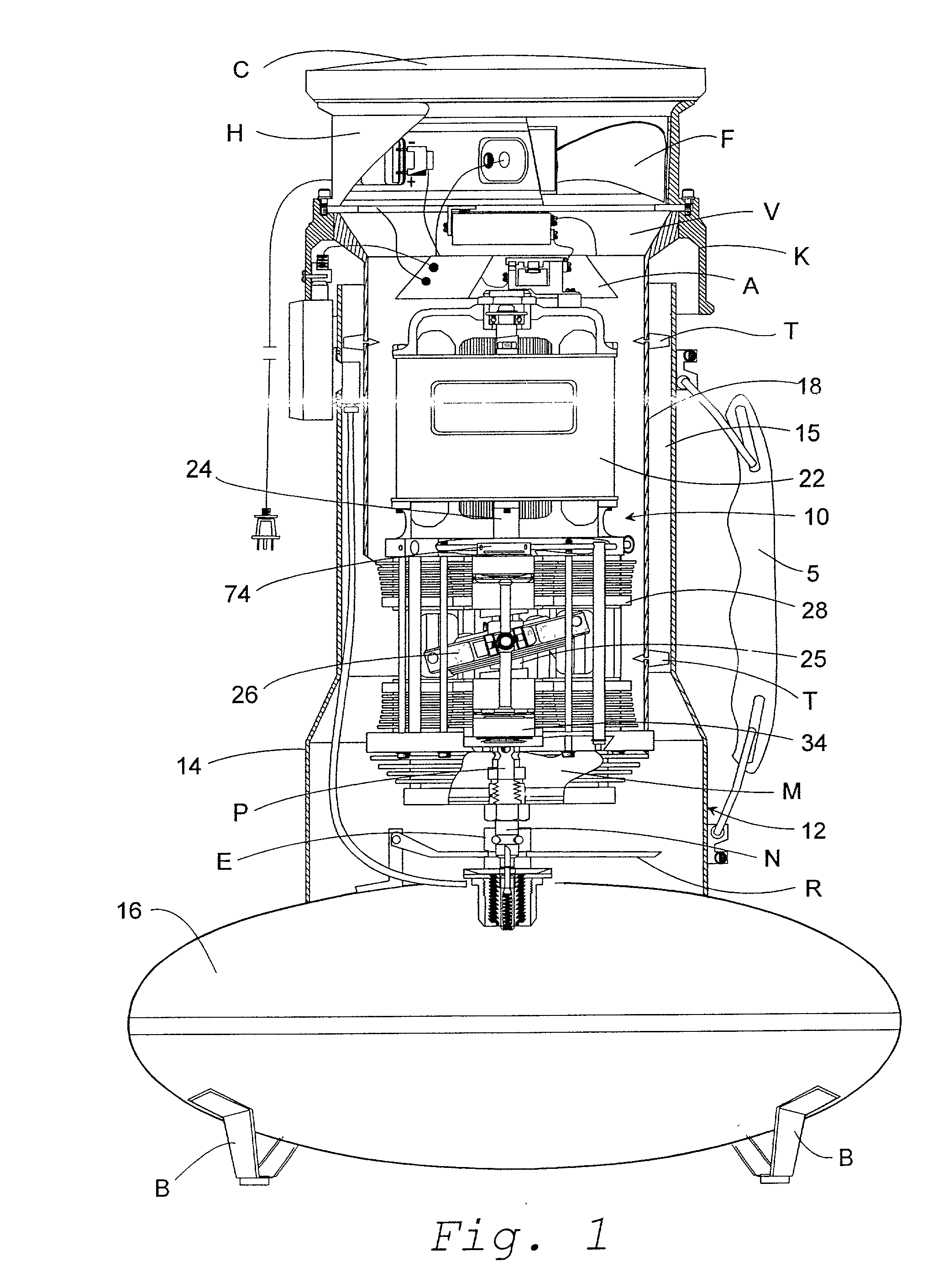
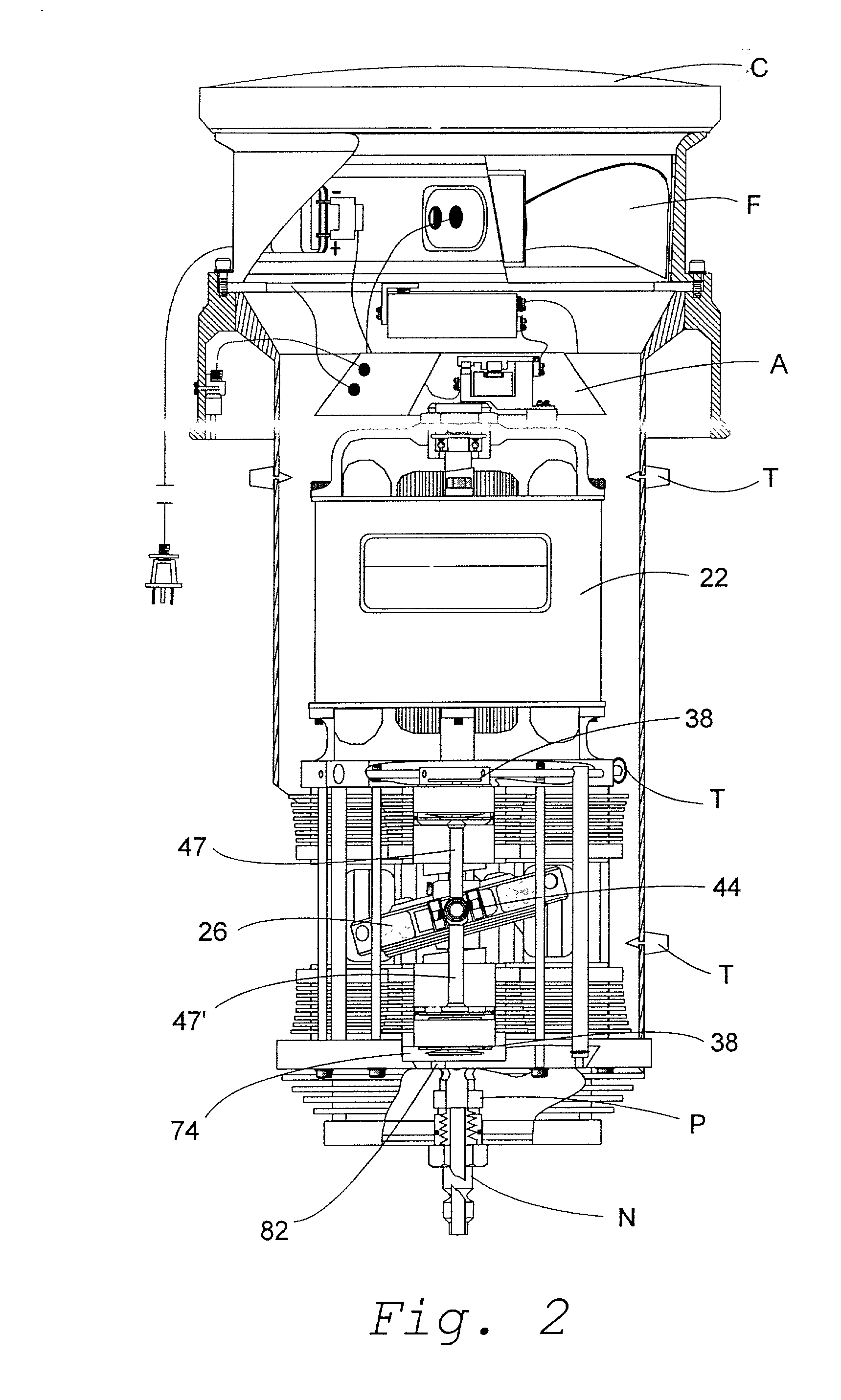
[0029] Referring in detail to the drawings, there is illustrated in FIGS. 1 to 3 a preferred form of air compressor assembly 10 releasably inserted in an air tank assembly 12, the latter including an upper tubular housing 14 with liner 15 and air chamber 16. The basic construction and arrangement of the air tank 12 corresponds to that described in my hereinbefore referred to U.S. Pat. No. 6,099,268 and is merely representative of various types of air tanks with which the air compressor 10 may be employed. Broadly, however, the tank is provided with a carrying strap S and a plurality of spacers T on outer wall 18 of the compressor assembly 10 to establish uniform spacing of the compressor 10 inside of the tank liner 15, and a discharge nipple N at the lower end of the compressor assembly 10 is insertable through a chuck E centrally located in the chamber 16. Although not shown, the chamber 16 is provided with an access port for a conventional discharge hose for removal of air from th...


PUM


Abstract

A portable, high capacity air compressor system for charging air tanks over wide pressure ranges with maximum volumetric efficiency is characterized by employing a shuttle piston assembly in which piston pairs are arranged with axially aligned cylinder pairs to reciprocate in response to precession of a wobble plate, and each of the pistons is further characterized by being of one-piece construction with a built-in leaflet-type intake valve in its piston head, and a universal connector between each of the piston pairs and wobble plate which is stabilized within a pair of guide rails.

Description

BACKGROUND AND FIELD OF INVENTION[0001] This invention relates to pneumatic compressor systems; and more particularly relates to a novel and improved air compressor for charging storage tanks.[0002] I previously devised a pneumatic pressure system for charging storage tanks and reference is made to U.S. Pat. No. 6,099,268, issued Aug. 8, 2000 entitled PNEUMATIC COMPRESSOR SYSTEM and co-pending Ser. No. 09 / 169,137, filed Jul. 18, 2000 entitled SWASH PLATE COMPRESSOR ASSEMBLY, and incorporated by reference herein. That system is characterized by being a swash plate type of air compressor capable of delivering pressures into the range of 200 psi and capable of charging different holding tanks so that each tank can serve as a self-contained source of pressurized air for various applications and resulted in decided improvements in terms of energy conversion, size and weight along with the noise associated with the operation of previous compressor designs.[0003] Among other features, the ...

Claims


Application Information

Patent Timeline
Patent Type & Authority Applications(United States)
IPC IPC(8): F04B27/08F04B27/10F04B39/00
CPCF04B27/0878F04B39/0022F04B39/0016F04B27/1036
Inventor PRESSEL, HANS-GEORG G.
Owner GREAT WEST GRP
Why Eureka
Try Eureka