Pervasive proactive project planner

a project planner and project technology, applied in the field of project planning engines, can solve the problems of complex projects with large design teams with complex methodologies and tools, difficult to gather data and keep the plan, and several flaws

Inactive Publication Date: 2003-04-24
IBM CORP
View PDF27 Cites 26 Cited by
  • Summary
  • Abstract
  • Description
  • Claims
  • Application Information

AI Technical Summary

Problems solved by technology

Today's complex projects often have large design teams with complex methodologies and tools.
Several flaws exist with this present system.
First, it is difficult to gather the data and keep the plan on track with all the individuals and activities within the project.
Another problem is that there i...

Method used


Image

  • Pervasive proactive project planner
  • Pervasive proactive project planner
  • Pervasive proactive project planner

Examples


Embodiment Construction

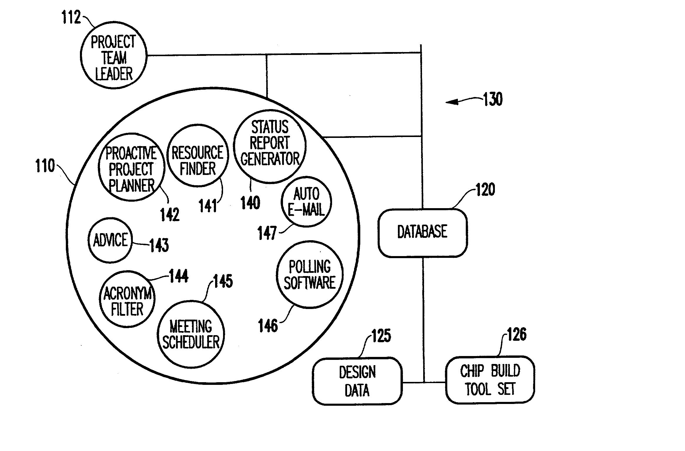
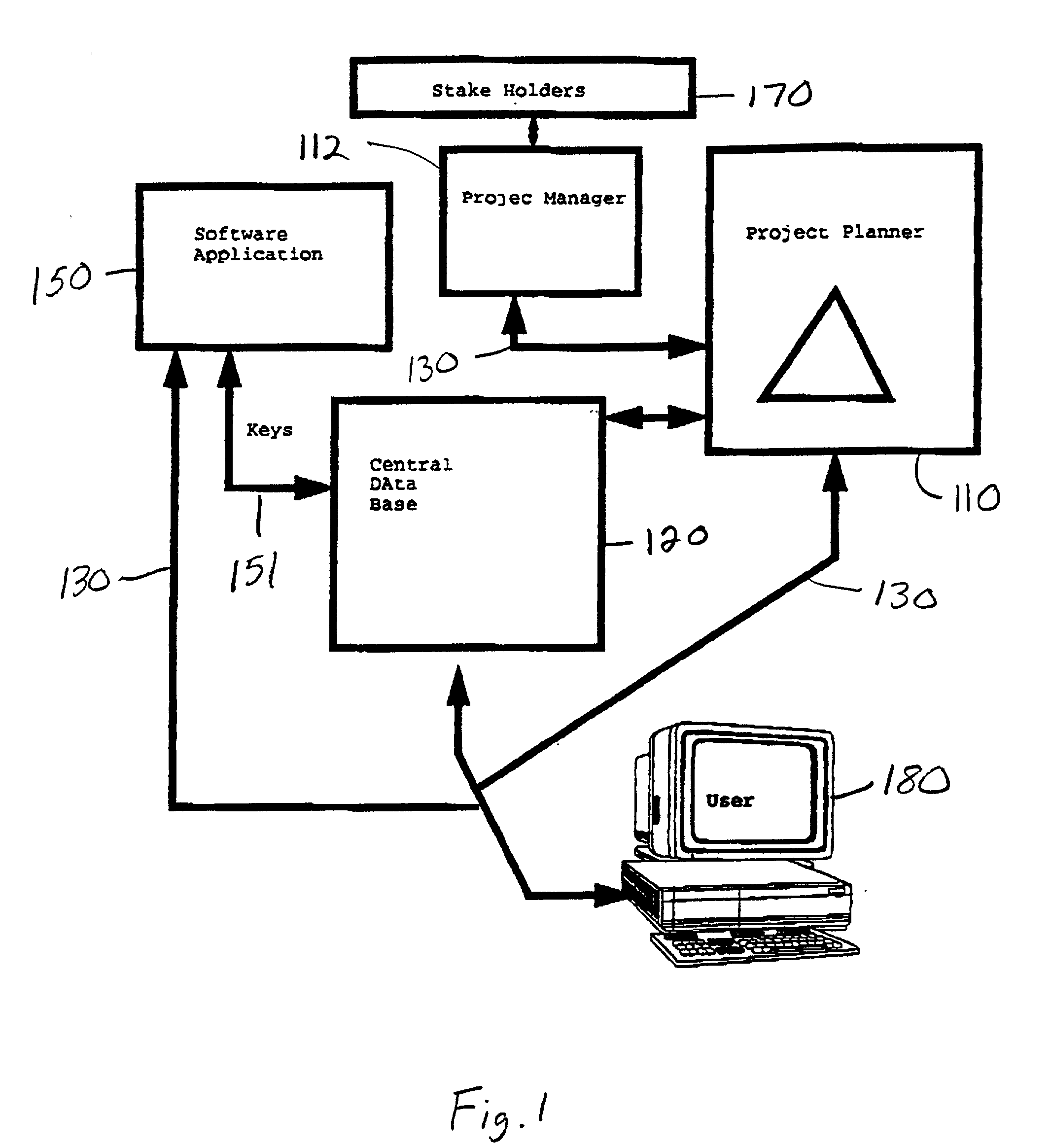
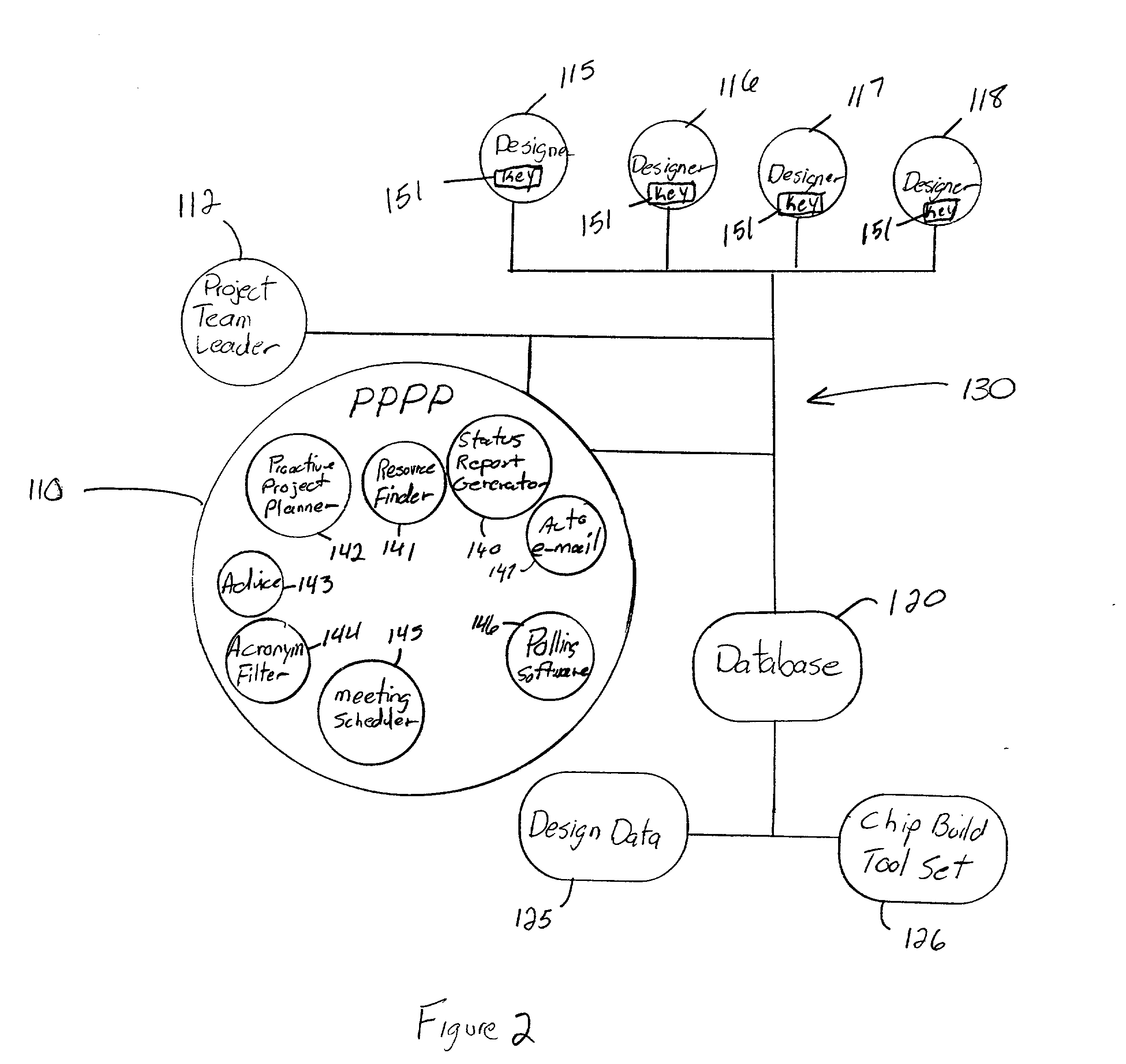
[0015] The invention, which is sometimes referred to herein as the Pervasive Proactive Project Planner (PPPP) fully integrates the project planning tool fully into the design methodology. With the invention, the project planner, project planner database / tool, the data, the designers, and the design tools are fully integrated into a cohesive and pervasive whole. The PPPP enables, tracks, alerts, and controls, with full automation, the design methodology.

[0016] FIG. 1 illustrates an overall system diagram using the invention. More specifically, FIG. 1 shows the inventive project planner as item 110. A central database is shown as item 120. A user 180 provides input to the project planner 110 and the central database 120. Many conventional software applications 150 can be utilized with the invention, such as timing control, test generation, simulation, or other design software tools that link software design and the data. For example, the software application 150 can access the central...


PUM


Abstract

A method and structure for coordinating resources to complete a design project prioritizes tasks to create a project plan, automatically notifies resources of task responsibilities and associated due dates based on the project plan through the use of encryption keys, controls access to the design data through the use of the encryption keys assigned to the resources, automatically monitors work being performed on tasks through a computerized network, and automatically notifies a project team leader of task completion status, overdue tasks, and tasks being ignored, based on the monitoring.

Description

[0001] 1. Field of the Invention[0002] The present invention generally relates to project planning engines and more particularly to an improved planning engine which automatically monitors the status of tasks being performed by resources.[0003] 2. Description of the Related Art[0004] Today's complex projects often have large design teams with complex methodologies and tools. Each tool may perform a specific task within the design flow. Teams may range from a few individuals on up to the hundreds. The need to control and track these activities have become a major focus within corporations today. The current method involves a graphical entry tool that allows the user to enter start and end dates and to link activities together, and to list the required resource (person) for the task.[0005] Another software execution tool then uses an e-mail system to send out reminder notes to the resource (person) as to the task that needs to be completed and the time frame it needs to be accomplishe...

Claims


Application Information

Patent Timeline
IPC IPC(8): G06Q10/06
CPCG06Q10/06G06Q10/063118G06Q10/063114
Inventor SWANKE, KARL V.VENTRONE, SEBASTIAN T.
Owner IBM CORP
Why Eureka
Try Eureka