Eureka AIR delivers breakthrough ideas for toughest innovation challenges, trusted by R&D personnel around the world.

Motor-fan unit particularly for a heating and/or air conditioning apparatus for a motor vehicle

Inactive Publication Date: 2003-05-08
VALEO SYST THERMIQUES
View PDF0 Cites 6 Cited by
  • Summary
  • Abstract
  • Description
  • Claims
  • Application Information

AI Technical Summary

Benefits of technology

[0005] The purpose of the invention is to solve the problem of cooling the control module while at the same time maintaining the possibility of housing the module as maintaining the possibility of housing the module as close as possible to the motor, so as to reduce electrical connections and bulk, while at the same time allowing easy removal and easy refitting of the control module where necessary, and allowing this module to be cooled effectively.
[0007] Thus, effective cooling can be obtained by exposing the radiator or radiators of the control module to the very turbulent air in the casing, while at the same time allowing easy removal and easy refitting of the control module because the latter, if need be, can be extracted from the motor-fan unit without the need to remove the motor support cover.
[0008] Advantageously, the control module comprises at least one radiator having several parts which are engaged through separate openings of corresponding shapes. Forming several openings, rather than a single opening which has necessarily to be larger, means that the rigidity of the motor support cover is not affected.
[0012] When the or each radiator penetrates at least partially by a short distance into the casing, or is even practically flush with the side thereof, a sufficient area for heat exchange with the air can be presented by increasing the dimensions, measured in the plane of the side of the casing, and thereby the dimensions of the opening or openings made in the motor support cover.

Problems solved by technology

One problem to be solved is that of cooling the motor control modules.
In addition, the presence of radiator fins penetrating into the air flow leaving the casing over a relatively great distance disturbs the flow and generates noise.

Method used


Image

  • Motor-fan unit particularly for a heating and/or air conditioning apparatus for a motor vehicle
  • Motor-fan unit particularly for a heating and/or air conditioning apparatus for a motor vehicle
  • Motor-fan unit particularly for a heating and/or air conditioning apparatus for a motor vehicle

Examples


Embodiment Construction

[0022] One embodiment of the invention will be described hereinafter in the context of an application to a heating and / or air conditioning apparatus for a motor vehicle. A motor-fan unit according to the invention can, however, be used for other applications requiring the generation of a flow of air or some other gas.

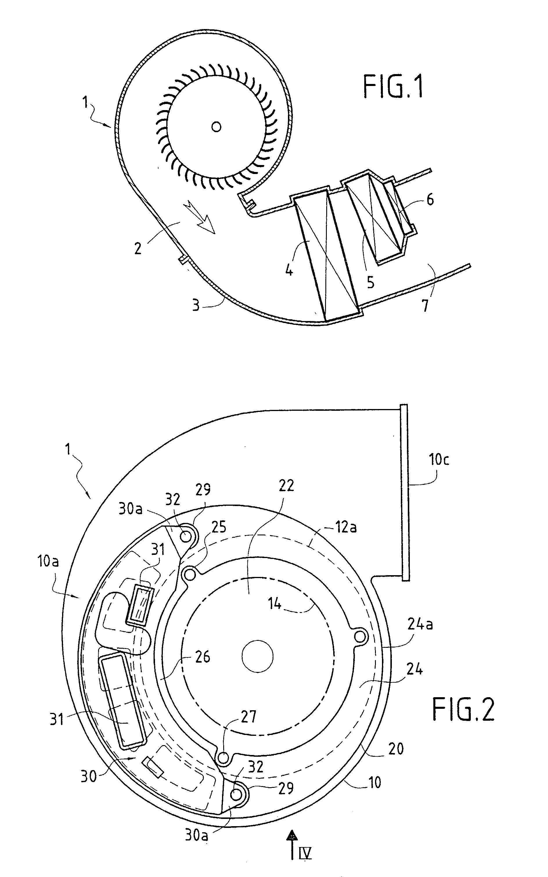
[0023] FIG. 1 provides a highly schematic depiction of a heating and air conditioning apparatus which comprises, in a very well-known way, a motor-fan unit 1, or blower, delivering an air flow 2 to a duct 3. Arranged in the latter are an evaporator 4 of a refrigeration circuit (when the air conditioning function is present), an air-liquid heat exchanger radiator 5 through which the vehicle engine coolant flows and possibly an electric top-up radiator 6. In air conditioning mode, air is diverted into a passage 7 bypassing the radiator 5. Downstream of the radiators 5 and 6, the duct 3 distributes the air to the outlets into the vehicle cabin. The air is distributed and p...


PUM


Abstract

The invention relates to a motor-fan unit (1) comprising a casing (10), a turbine (12) housed in the casing to generate an air flow therein, a motor (14) for driving the turbine, a support (20) for the motor, also forming a cover that closes off the casing on one side (10a) thereof, and a motor control module (30) associated with at least one radiator dissipating heat generated by components of the control module and exposed to the air flow generated in the casing. The control module (30) is mounted on the motor support cover (20) on the outside thereof and the radiator is at least partially engaged through at least one opening made in the motor support cover and opening laterally into the casing.

Description

[0001] The invention relates to a motor-fan unit particularly for a heating and / or air conditioning apparatus, in particular for a motor vehicle.[0002] For such an application, it is known practice to use a motor-fan unit of the type comprising a casing, a turbine housed in the casing to generate an air flow therein, a motor for driving the turbine, a support for the motor also forming a cover that closes off the casing on one side thereof, and a module for controlling the motor to allow the motor speed to be varied as needed.[0003] One problem to be solved is that of cooling the motor control modules. It is known practice for one or more radiators to be associated with the control module for this purpose in order to dissipate the heat generated by the electrical and electronic components of this module. In particular, it has been proposed for the radiator or radiators to be exposed to the air flow generated in the casing, but by arranging the radiators at the casing outlet, which f...

Claims


Application Information

Patent Timeline
IPC IPC(8): F04D25/08F04D29/42F04D29/58
CPCF04D25/08F04D29/4226H02K11/0073H02K7/14F04D29/584H02K11/33F04D25/06F04D29/5813H05K7/20918
Inventor BOUCHERET, BERNARDTALAUCHER, STEPHANEGEROUX, PIERRE-ARNAUD
Owner VALEO SYST THERMIQUES
Why Eureka
Eureka Blog
Learn More