

Fuel cell separator plate and method for producting it
a technology of separator plate and fuel cell, which is applied in the direction of cell components, final product manufacturing, sustainable manufacturing/processing, etc., can solve the problems of reducing the gas tightness of the fuel cell, and it is difficult to meet the above conditions simultaneously, and achieves excellent gas tightness and low contact resistance
Active Publication Date: 2003-05-08
HONDA MOTOR CO LTD
View PDF9 Cites 23 Cited by
- Summary
- Abstract
- Description
- Claims
- Application Information
AI Technical Summary
Benefits of technology
[0004] Accordingly, an object of the present invention is to provide a fuel cell separator plate having low contact resistance with an electrode and excellent gas tightness, and a method for producing such a fuel cell separator plate.
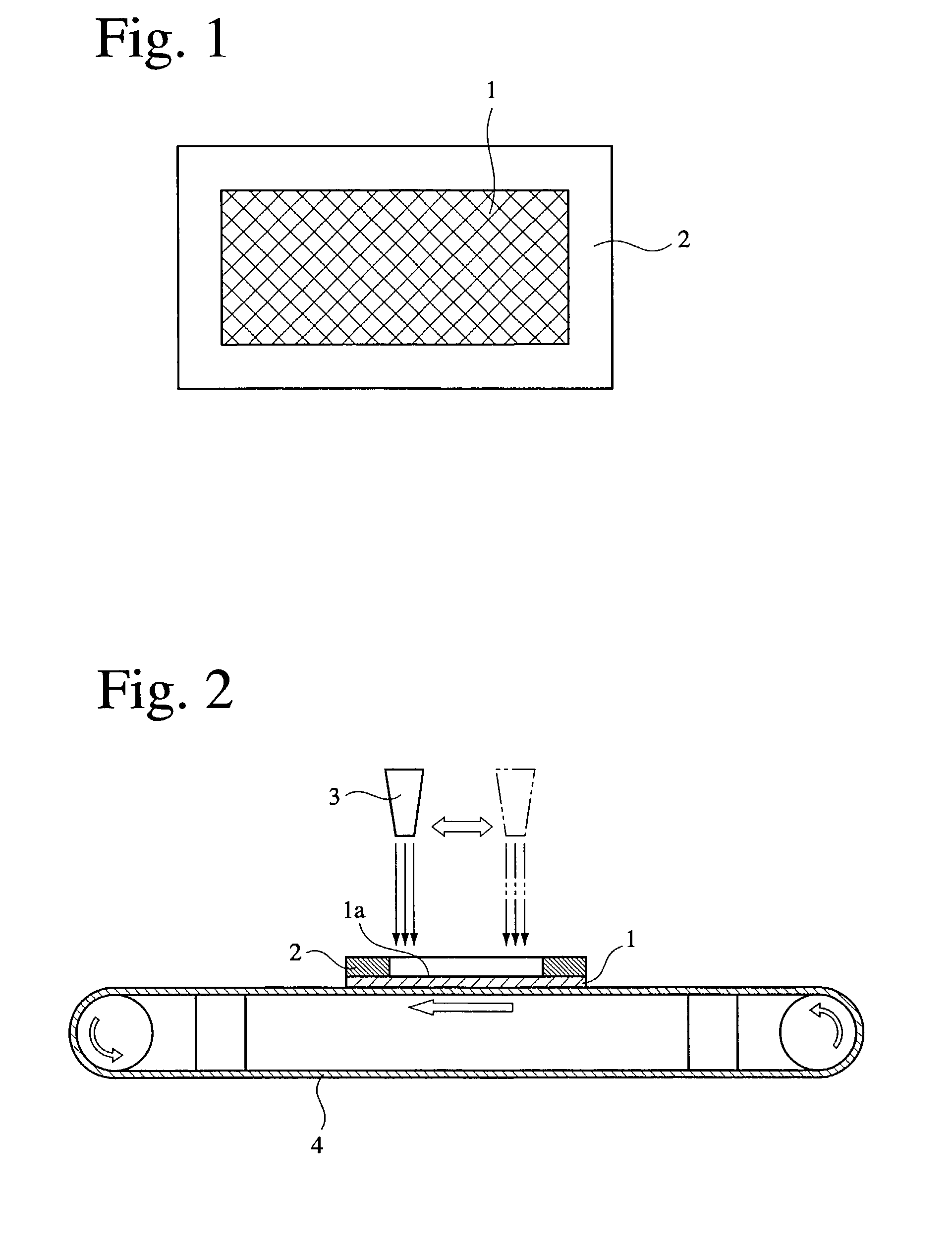
[0005] As a result of intensive research in view of the above object, the inventors have found that the contact resistance of the separator plate with the electrode can be reduced by surface-roughening a portion of the separator plate, which is to be in contact with the electrode, and that the gas tightness can be increased with gas leak suppressed by keeping smooth a surface of a sealing portion of the separator plate, which does not contact with the electrode. The present invention has been achieved based on these findings.
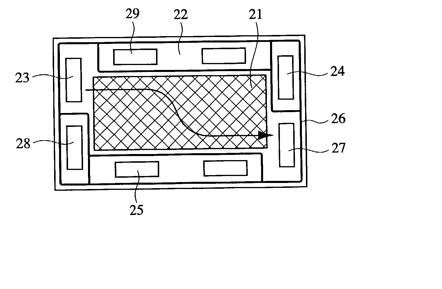
[0026] The fuel cell separator plate of the present invention is characterized in that the surface roughness (Rmax) of a portion in contact with an electrode is larger than that of a sealing portion. In a separator plate molded from carbon powder and a resin such as a thermosetting resin as a binder, the resin tends to be segregated in a surface portion because of the difference in their melting temperatures. If such separator plate is used without treatment, it exhibits high electric resistance (contact resistance) because the resin covering the surface of the separator plate is an electric insulator, resulting in large voltage loss and thus low performance. To decrease contact resistance with an electrode, the fuel cell separator plate of the present invention is deprived of a resin in advance in a surface area, which is to be brought into contact with an electrode, thereby having a large surface roughness (Rmax) in a portion in contact with the electrode. On the other hand, if a resin were removed from the separator plate in a surface area in its sealing portion, the sealing portion would have a roughened surface, failing to secure its tightness for a fuel gas, an oxidizing gas and cooling water. Accordingly, the sealing portion is kept in an as-molded state without surface treatment, so that it can suppress leak because of increased gas tightness. Thus, with a portion in contact with an electrode provided with a higher surface roughness (Rmax) than that of a sealing portion, the separator plate can have decreased contact resistance and increased gas tightness simultaneously.
[0032] Carbon powder and a resin are mixed preferably at such a ratio that the carbon powder is 60-85% by weight and the resin is 40-15% by weight, both based on the total amount. Carbon powder and the resin may be those specifically described above. The mixing of carbon powder and a resin can be carried out by usual blending machines such as a kneader, a compression kneader, a double-screw blender, a ball mill, a mixer, etc. Usable in this case if necessary is a method in which the resin is dissolved in a proper organic solvent such as alcohol, ether, etc. to lower its viscosity, with the organic solvent removed after blending with carbon powder.
[0046] A fuel gas, an oxidizing gas and a coolant should pass through separate paths to avoid their mixing. In addition, it is necessary to prevent these reaction gases and cooling medium from leaking from a fuel cell. Therefore, to supply a fuel gas, an oxidizing gas, humidifying water and a cooling medium to each cell, seals are provided around holes penetrating stacks, in a periphery of each unit fuel cell composed of an electrolyte membrane, catalytic electrode layers and gas diffusion layers, around flow paths for a coolant passing along a surface of the separator plate for cooling the separator plate, and in a periphery of each separator plate on both surfaces, etc. Because the fuel cell separator plate of the present invention has a large surface roughness only in a portion in contact with the electrode, and has a sealing portion kept smooth, it is excellent in gas tightness by sealing.
Problems solved by technology
However, the roughening of the separator plate by a surface treatment, etc. to reduce contact resistance between the separator plate and an electrode leads to decrease in the gas tightness of the fuel cell.
Accordingly, it is difficult to simultaneously meet all of the above conditions required for the separator plate.
Method used
View moreImage
Smart ImageViewing Examples

Examples
example 2
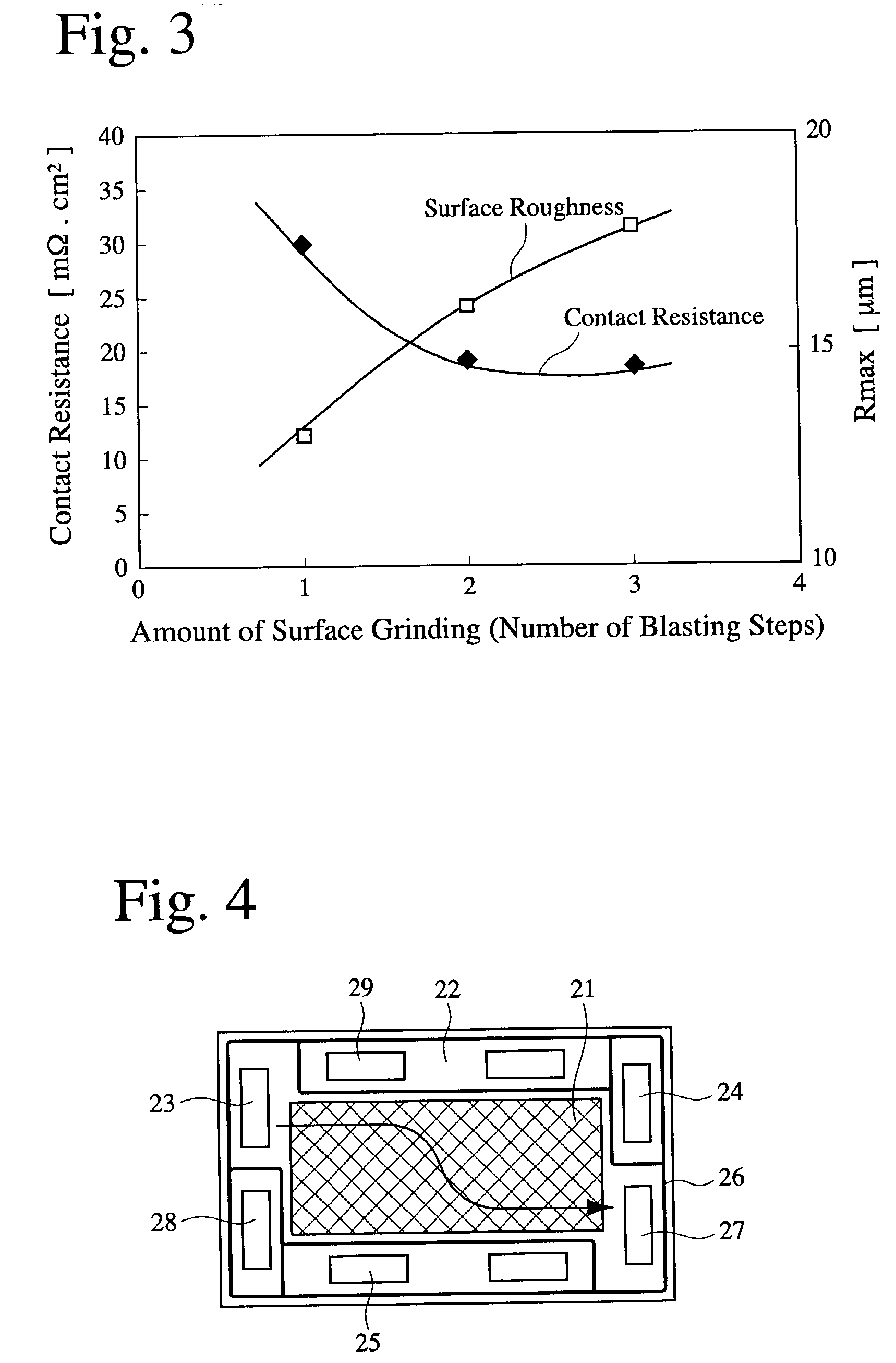
[0061] Each fuel cell separator plate was produced in the same manner as in Example 1. With blasting conditions set at three levels of strong, middle and weak as shown in Table 2, each surface of the resultant separator plates was roughened. Next, a battery unit was produced in the same manner as in Example 1, and its voltage loss was measured with electric current of 300 A supplied. The measurement results are shown in Table 2 and FIG. 8.
Login to View More PUM
| Property | Measurement | Unit |
|---|---|---|
| surface roughness | aaaaa | aaaaa |
| surface roughness | aaaaa | aaaaa |
| surface roughness | aaaaa | aaaaa |
Abstract
A fuel cell separator plate comprising a portion in contact with an electrode, and a sealing portion provided around the contact portion, the contact portion having a larger surface roughness (Rmax) than that of the sealing portion. It is preferably a molded separator plate made of a composite carbon material comprising carbon and a thermosetting resin.
Description
[0001] The present invention relates to a fuel cell separator plate having low contact resistance with an electrode and excellent gas tightness.DESCRIPTION OF PRIOR ART[0002] Because a solid polymer electrolyte fuel cell can generate electricity at lower temperatures and at higher output density than other fuel cells such as a phosphoric acid fuel cell, etc., it is expected that the solid polymer electrolyte fuel cell is used not only as a power supply for automobiles but also as a small mobile power supply. The solid polymer electrolyte fuel cell may be a stack constituted by unit fuel cells (membrane-electrode assemblies) laminated via separator plates, each unit fuel cell being constituted by an electrolyte membrane, which is a high-molecular-weight ion-exchange membrane such as a fluororesin-type ion-exchange membrane usually having a sulfonic acid group, etc., and catalytic electrodes carrying a platinum catalyst formed on both surfaces of the electrolyte membrane. Among these ...
Claims
Login to View More Application Information
Patent Timeline
 Patent Type & AuthorityApplications(United States)
IPC IPC(8): C08K3/04C08L101/00H01M8/02H01M8/04H01M8/10
CPCH01M8/0202Y02E60/50H01M2008/1095H01M8/0226Y02P70/50
InventorNAKANISHI, YOSHIHIROKOSAKA, YUICHIRONAGOSHI, KENTARO
OwnerHONDA MOTOR CO LTD