
Thermoelectric component

Inactive Publication Date: 2003-05-15
ROBERT BOSCH GMBH
View PDF14 Cites 10 Cited by
  • Summary
  • Abstract
  • Description
  • Claims
  • Application Information

AI Technical Summary

Benefits of technology

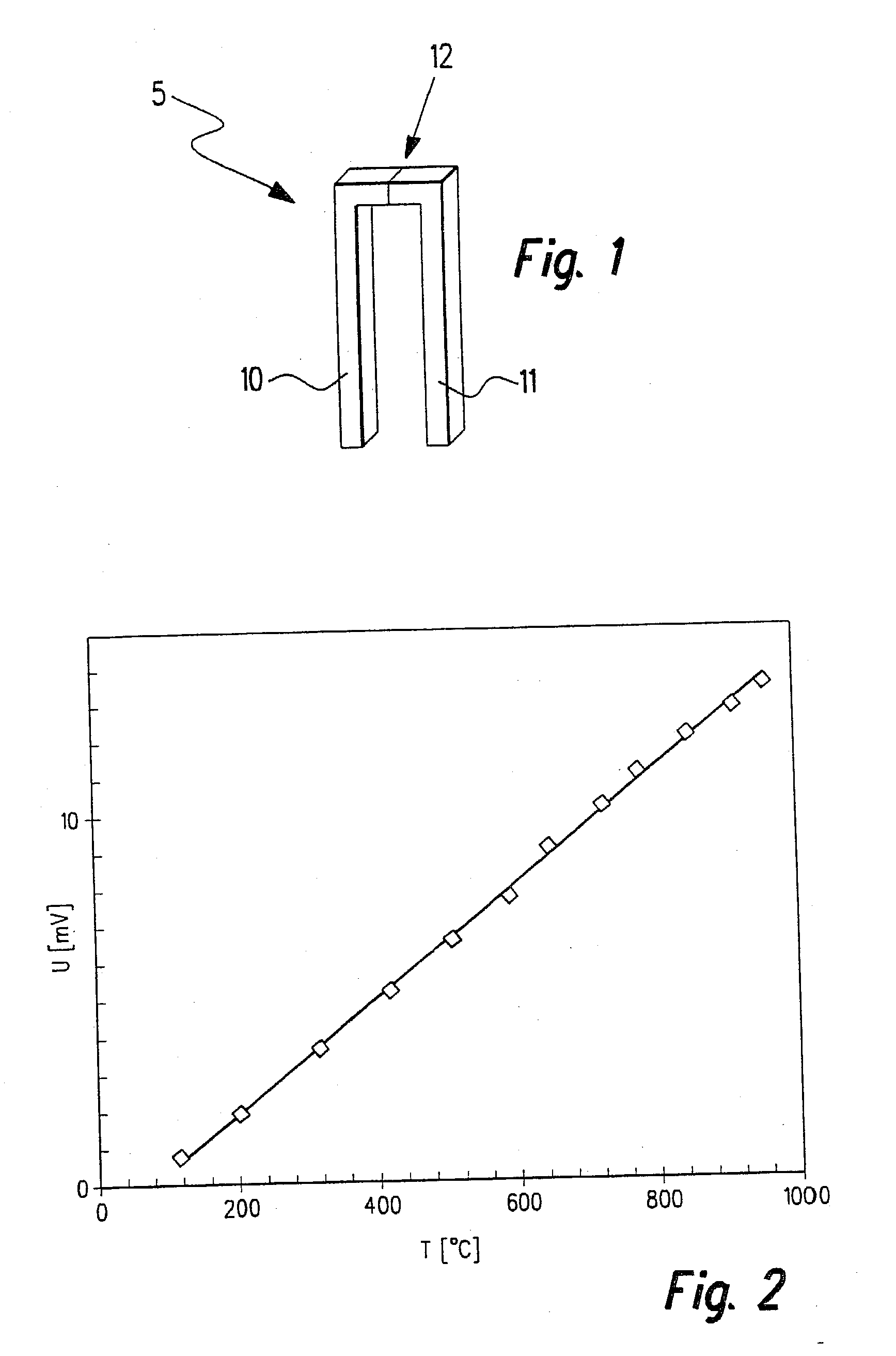
[0004] The thermoelectric component according to the present invention may provide the advantage that it has a very good service life and very good constancy in the thermoelectric voltage that occurs, even at high temperatures and reactive gas atmospheres, a typical service life being considered to be five years. In particular, the thermoelectric component according to the present invention, when used as a thermocouple, permits making temperature measurements of up to 1300.degree. C. as well as in an oxidizing and also in a reducing atmosphere, at a precision of less than .+-.10.degree. C. The thermoelectric component may have a short response time to temperature changes, which is typically less than one second.
[0006] Because of its good temperature stability and resistance with respect to reactive gas atmospheres, in the thermoelectric component according to the present invention, one may furthermore do without a ceramic or metallic protective tube, so that its use as a thermocouple makes possible accurate and, at the same time, fast temperature measurement.
[0007] The thermoelectric component according to the present invention may provide the advantage of a long service life expectation, even in reactive gas atmospheres, at simultaneously high temperature resolution and rapid response time. Beyond that, it can be manufactured cost-effectively and, particularly when used as a thermocouple, it has typical thermoelectric voltages in the mV range, which are easily measurable.

Problems solved by technology

In using thermocouples for measuring temperatures, one frequently runs into limits of material load capacity with regard to temperature and application atmosphere.
Thus at present, in using thermocouples for a temperature range up to 1500.degree. C. based on PtRh / Pt elements, in extended use above 1000.degree. C., there frequently appears a drift in the thermoelectric voltage, and simultaneously, a considerable deterioration of the mechanical properties on account of creep processes.
In addition, PtRh / Pt thermocouples are very expensive to produce, and therefore not usable in certain applications.

Method used


Image

  • Thermoelectric component
  • Thermoelectric component

Examples


Embodiment Construction

[0054] The exemplary embodiments further explained, first of all relate to polymeric precursor materials, provided with filler materials, which are convertible into ceramic materials by pyrolysis. Such precursor materials or filler materials, respectively, are known from EP 0 412 428 B1 or from DE 195 38 695 A1. It is also known from these that one can produce molded articles using pyrolysis, by the addition of filler materials to the polymeric precursor materials used. In this connection, the specific resistance of the ceramic molded articles obtained can be set both by the choice of the filler materials and by the choice of the polymeric precursor material.

[0055] As the polymeric precursor materials for the exemplary embodiments which are further explained, polymers are particularly suitable which are convertible by pyrolysis into ceramic materials based on Si--C compounds, Si--C--N compounds, Si--Ti--C--O compounds, Si--C--O compounds, Si--B--C--N compounds, Si--B--C--O compounds...


PUM


Abstract

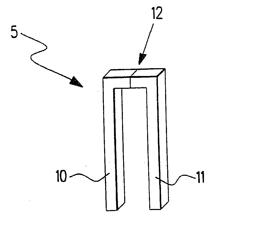
A thermoelectric component (5) is proposed, which has a first and a second element (10, 11) which, in the vicinity of a contact point (12), are in contact with each other, particularly in the form of a thermal contact. Furthermore, in this connection, first element (10) and / or second element (11) have a ceramic material at least in one vicinity of contact point (12). The proposed component (5) is especially suitable as a thermocouple for measuring temperature based on the Seebeck effect, or for use in a Peltier element as a thermoelectric heating element or cooling element based on the Peltier effect.

Description

[0001] The present invention relates to a thermoelectric component, e.g., a thermocouple.BACKGROUND INFORMATION[0002] In using thermocouples for measuring temperatures, one frequently runs into limits of material load capacity with regard to temperature and application atmosphere. In using thermocouples for a temperature range up to 1500.degree. C. based on PtRh / Pt elements, in extended use above 1000.degree. C., there frequently appears a drift in the thermoelectric voltage, and simultaneously, a considerable deterioration of the mechanical properties on account of creep processes. In particular, during contact with carbon in such thermocouples, often metal carbides will form, which change the Seebeck coefficient and the mechanical properties of the thermocouple. In addition, PtRh / Pt thermocouples are very expensive to produce, and therefore not usable in certain applications.[0003] It is an object of the present invention to make available a thermoelectric component that may be ap...

Claims


Application Information

Patent Timeline
IPC IPC(8): H01L35/22H01L35/30H01L35/34
CPCH01L35/34H01L35/22H10N10/855H10N10/01
Inventor ENGEL, CHRISTINEDRESSLER, WOLFGANGKLONCZYNSKI, ALEXANDERBOEDER, HORST
Owner ROBERT BOSCH GMBH
Learn More