Intelligent motor drive module with injection molded package

Inactive Publication Date: 2003-06-12
INTERNATIONAL RECTIFIER COEP
View PDF6 Cites 50 Cited by
  • Summary
  • Abstract
  • Description
  • Claims
  • Application Information

AI Technical Summary

Benefits of technology

0003] Intelligent power modules (IPMs) are well known devices for driving various types of motors. These devices at minimum include a plurality of power switching devices and respective integrated circ

Problems solved by technology

These elements are expensive and thu

Method used


Image

  • Intelligent motor drive module with injection molded package
  • Intelligent motor drive module with injection molded package
  • Intelligent motor drive module with injection molded package

Examples


Embodiment Construction

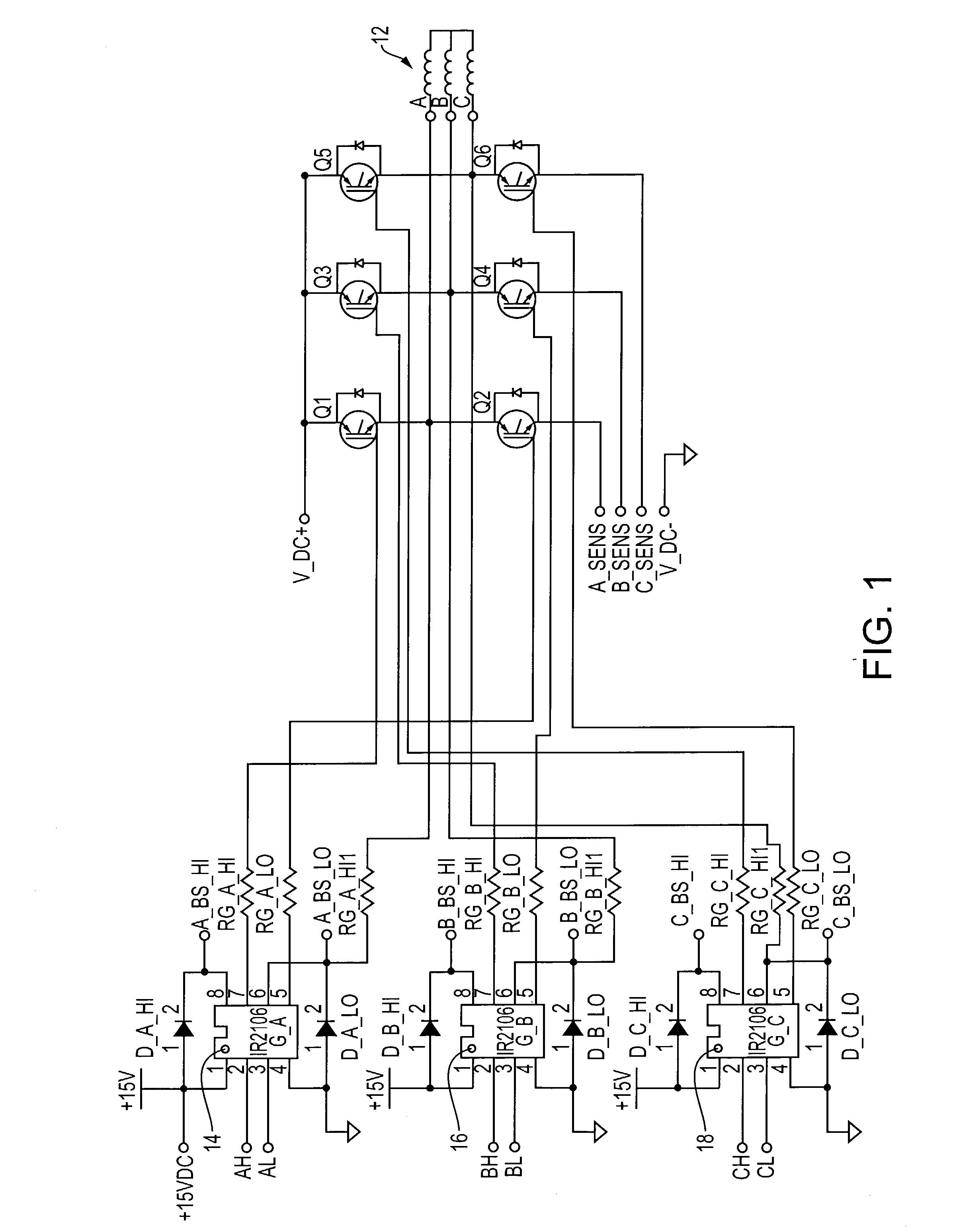
[0020] FIG. 1 shows a motor control circuit 10 for controlling a three-phase motor 12. Motor control circuit 10 includes three phase-control circuits each for controlling a phase winding A, B, C of three-phase motor 12. Each phase-control circuit includes a power stage, which may comprise two series-connected power semiconductor devices (e.g., Q.sub.1-Q.sub.2 pair; Q.sub.3-Q.sub.4 pair; Q.sub.5-Q.sub.6 pair), and power semiconductor driver circuits 14, 16, 18. The power semiconductor devices may be MOS-gated devices such as MOSFETs or IGBTs. Power semiconductor driver circuits 14, 16, 18 may be integrated circuits having drivers with independent high and low side referenced output channels. One such integrated circuit is provided by International Rectifier, the assignee of this application, and sold under the designation IR2106.

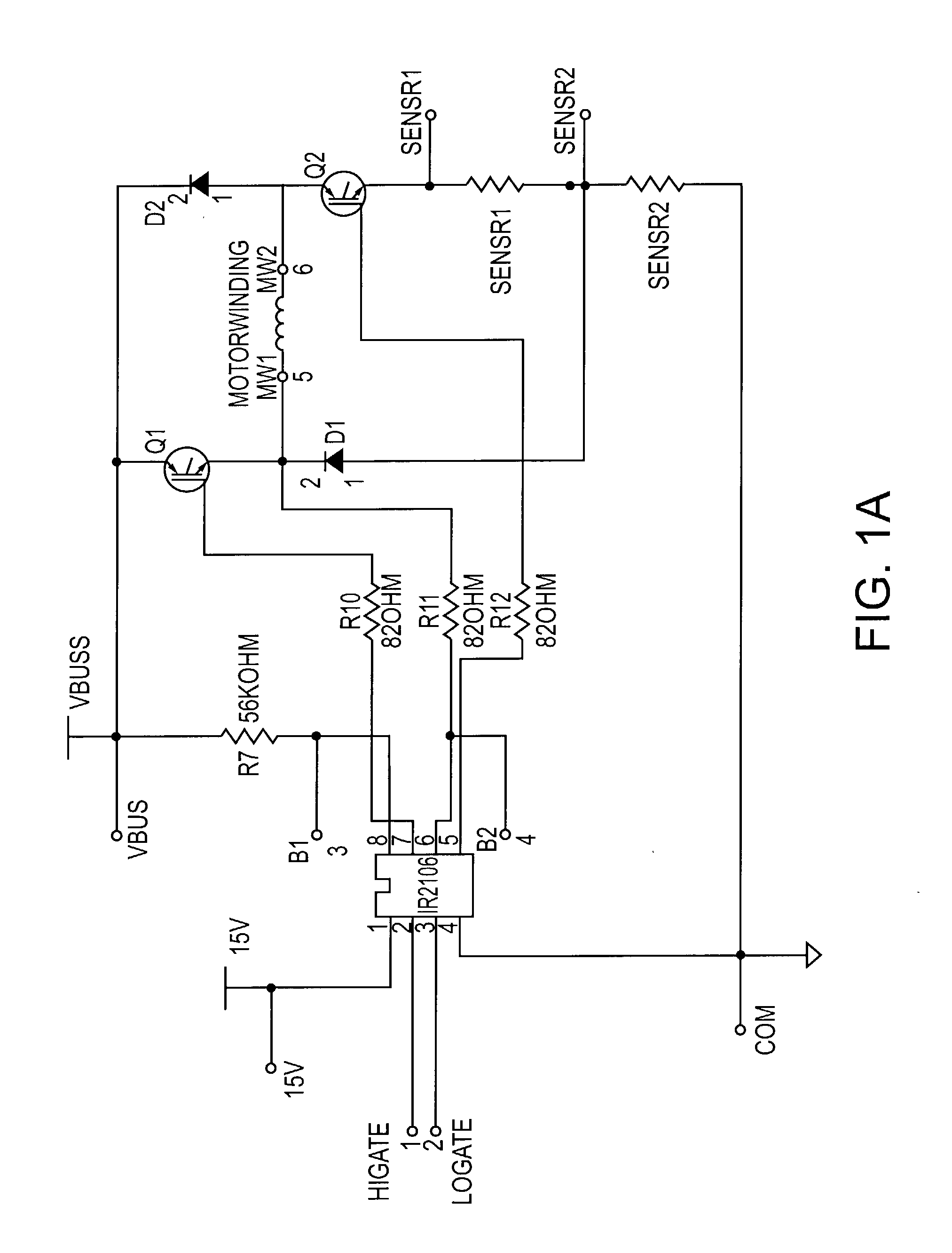
[0021] FIG. 1A shows a circuit diagram for driving a motor winding MW1-MW2 of a switched-reluctance motor, which may also be incorporated in a power module a...


PUM


Abstract

A power module having a lead frame with a plurality of power switching devices and a plurality of driving devices mounted thereon. The driving devices control the power switching devices to provide power to a plurality of output leads via first wire bonds. The first wire bonds are substantially parallel to each other between the power switching devices and the output leads. Each power switching device preferably includes a power semiconductor device and a diode, the diodes and power switching devices being interconnected by second wire bonds which are also substantially parallel to each other. The power switching devices preferably comprise bare semiconductor die mounted on the lead frame, the lead frame and power switching devices being enclosed in a molded package. The molded package are preferably formed by transfer-molding or injection-molding.

Description

[0001] This application is based on and claims priority of U.S. Provisional Patent Application Serial No. 60 / 339,158, filed Dec. 11, 2001, the disclosures of which are incorporated by reference herein.[0002] The application relates to a power module, and more particularly to a power module for housing a motor control circuit.BACKGROUND AND SUMMARY OF DISCLOSURE[0003] Intelligent power modules (IPMs) are well known devices for driving various types of motors. These devices at minimum include a plurality of power switching devices and respective integrated circuits (ICs) for controlling the devices. Due to their high degree of integration IPMs provide for, among other advantages, reduced design time and improved reliability, and generally more compact sizes.[0004] Most IPMs use insulated metal substrates (IMS) or direct bonded copper (DBC) substrates. These elements are expensive and thus add to the overall cost of the IPM. Thus, it is desirable to have a solution that improves the co...

Claims


Application Information

Patent Timeline
IPC IPC(8): H01L25/07H01L23/495H01L25/16H01L25/18H02M7/5387
CPCH01L23/49562H01L25/16H01L2224/49171H01L2924/01077H02M7/53871H02M2007/4815H02M2007/53878H01L2924/13055Y02B70/1441H01L24/49H01L2924/13091H01L2224/48137H01L2924/00H01L24/48H01L2224/05599H01L2224/45099H01L2224/85399H01L2924/00014H01L2924/14H01L2224/0603H01L2924/19105H01L2924/19107H01L2924/181Y02B70/10H02M7/53878H02M7/4815H01L2224/45015H01L2924/207
Inventor CONNAH, GLYNPEARSON, GEORGE W.STEERS, MARK
Owner INTERNATIONAL RECTIFIER COEP
Why Eureka
Try Eureka