

Method for preventing plate type heat exchanger from blockage
a technology of heat exchanger and plate, which is applied in the direction of indirect heat exchanger, laminated elements, lighting and heating apparatus, etc., can solve the problems of reducing production efficiency, causing blockage between adjacent plates, and unduly expensive methods
Inactive Publication Date: 2003-06-19
NIPPON SHOKUBAI CO LTD
View PDF8 Cites 29 Cited by
- Summary
- Abstract
- Description
- Claims
- Application Information
AI Technical Summary
Benefits of technology
[0015] According to this invention, by setting the width of the plate flow path and the average rate of flow of the gas per unit cross-sectional area of the plate flow path in respectively specified ranges, it is made possible in the processing of an discharge gas containing an easily blocking substance as in the apparatus for the production of (meth)acrylic acid to prevent the plate type heat exchanger from blockage or to operate the plate type heat exchanger continuously a long time without an interruption.
[0016] Further, this invention is aimed at providing for the heat exchange of a gas containing an easily blocking substance in the plate type heat exchanger, and provides a method for preventing the plate type heat exchanger from blockage by disposing a gas dispersion plate in a gas introduction port for the gas containing the easily blocking substance.
[0017] According to this invention, since the gas containing the easily blocking substance is uniformly dispersed in the heat exchange part in the plate type heat exchanger, the occurrence of the blocking substance during the uneven supply of the gas in the heat exchange part can be repressed. When the gas containing the easily blocking substance contacts a structure while the gas is being dispersed unevenly, the gas adheres to the surface of contact and accumulates thereon and eventually gives rise to a blockage. The method of this invention succeeds in repressing the adhesion and accumulation of the gas to the surface of contact and preventing the eventual formation of blockage because the disposition of the dispersion plate results in enabling the gas to be evenly dispersed in the heat exchange part.
Problems solved by technology
When the heat-exchanging gas happens to contain an easily blocking substance, it often gives rise to blockage between the adjacent plates.
When the device is intended for continuous mass production as in the production of a general-purpose chemical substance, the stop of the device forms the cause for lowering the efficiency of production.
This method, however, proves unduly expensive.
If the cross-sectional area in the gas introduction port is equalized with that in the inlet part of the heat exchange part, the gas pipes will have to be enlarged and the cost of equipment will be consequently heightened.
No contrivance whatever for uniformizing the supply of gas, however, has been made for the heat exchange part destined to introduce the heat-exchanging gas.
Particularly when the heat-exchanging gas contains an easily blocking substance, an uneven ratio of heat exchange results in local generation of a blocking substance due to adhesion or accumulation of the easily blocking substance.
When the gas containing the easily blocking substances is subjected to heat exchange as described above, the uneven supply of the gas degrades the thermal efficiency and the concentration of the feed gas results in generating the blocking substance in part of the heat exchange part and consequently compelling the entire device to stop its operation.
The use of this gas brings such problems as inducing adhesion of the blocking substance to the heating surface and consequently degrading the efficiency of heat transfer.
All these disadvantages still remain yet to be solved.
When the gas containing the easily blocking substance contacts a structure while the gas is being dispersed unevenly, the gas adheres to the surface of contact and accumulates thereon and eventually gives rise to a blockage.
These steps invariably generate a discharge gas to be wasted and this gas possibly entrains an easily blocking substance.
In the plate type heat exchanger, when the gas destined to exchange heat through the plates is a gas which contains an easily blocking substance, the flow paths which passes this gas has the possibility of posing the problem of blocking the flow path with the easily blocking substance.
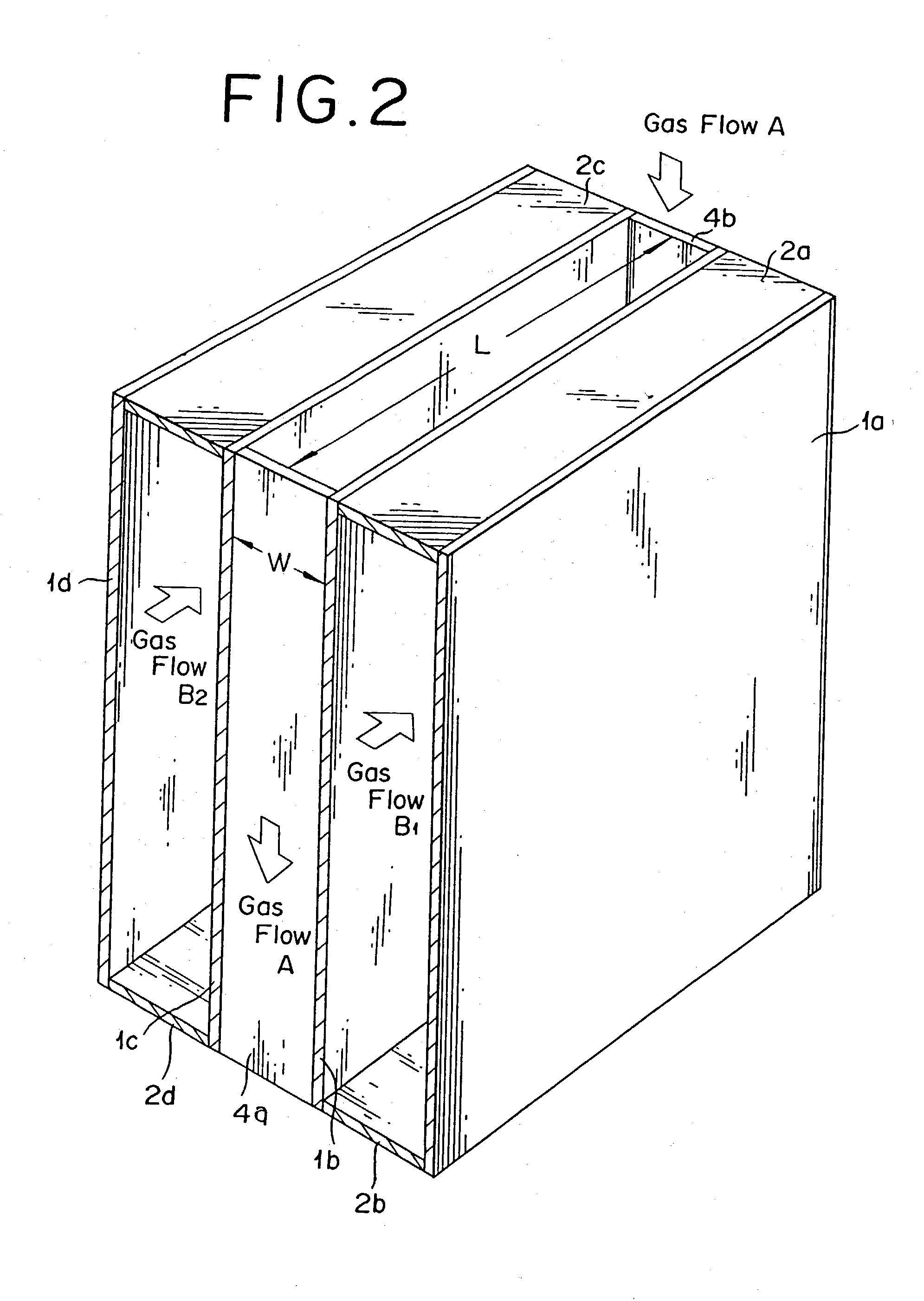
If the width of the flow path on the plate is less than 6 mm, the easily blocking substance will easily form bridges between the adjacent plates. conversely, if the width exceeds 25 mm, the excess be at a disadvantage in lowering the average flow rate of the gas containing the easily blocking substance and exalting the adhesion of a deposit to the plates 1b, 1c which are heating surfaces.
The excess also brings such economic disadvantages as lowering the coefficient of heat transfer of the plates and necessitating an addition to the size of the heat exchanger.
This measure is not economical because it requires additional plates in the direction of flow of the gas containing the easily blocking substance with a view to securing the heating surfaces for the exchange of heat, compels the relevant devices to incur exaggerated pressure loss, obliges blowers and other devices to enlarge their sizes, and consequently boosts the running cost of the apparatus.
If the average flow rate is less than 3 m / s, the shortage will be at a disadvantage in inducing a decline in the coefficient of heat transfer of the plates, preventing the heat exchange from proceeding sufficiently, and aggravating adhesion of blocking substance to the plates which are heating surfaces.
Conversely, if the average flow rate exceeds 15 m / s, the excess will be at a disadvantage in aggravating adhesion of blocking substance to the plates by decreasing the width of flow paths on the plates.
It also brings such economic disadvantages as compelling the devices to incur exaggerated pressure loss, obliging blowers and other devices to enlarge their sizes, and consequently boosting the running cost of the apparatus.
This measure is at a disadvantage in requiring additional plates in the direction of flow of the gas containing the easily blocking substance with a view to securing the heating surfaces for the exchange of heat and similarly compelling the relevant devices to incur exaggerated pressure loss.
The gas containing the easily blocking substance, therefore, does not contain the polymerization inhibitor sufficiently.
When this gas is partially cooled, the readily polymerizing substance tends to give rise to a blockage in consequence of condensation.
The condensation and the generation of a blockage occur easily when the ratio of heat exchange is not uniform and the condensate is suffered to stagnate partly for a relatively long time.
If the opening ratio is less than 10%, the shortage will be at a disadvantage in failing to permit the uniform dispersion of the gas appropriate for the perforation of the plate and suffering the dispersion plate to give rise to blockage.
Conversely, if the opening ratio exceeds 60%, the excess will be at a disadvantage in increasing the amount of the gas passing the dispersion plate and consequently bringing the possibility of obstructing uniform dispersion of the gas.
If the size is less than 20 mm.sup.2, the shortage will be at a disadvantage in inducing the holes to be blocked, impeding the final uniform dispersion of the gas in the heat exchange part, and possibly compelling the heat exchange part to give rise to blockage.
Conversely, if the size exceeds 1000 mm.sup.2, the excess will be at a disadvantage in not enabling the gas dispersion plate to produce sufficient dispersion of the gas after elapse of time and possibly suffering the heat exchange part to give rise to blockage.
If the distance (Ln) is less than 0.5 times the diameter (An), the shortage will be at a disadvantage in suffering the gas entering the port for the introduction of the gas to collide in an undispersed state against the surface of the gas dispersion plate and therefore tending to block the surface of the gas dispersion plate.
Conversely, if this distance exceeds 3.0 times the diameter (An), the excess will be at a disadvantage in rendering the dispersion of the gas insufficient because of the insufficiency of amount of the gas allowed to contact the gas dispersion plate.
Further, if the distance (Lt) is less than 1.0 times the distance (Ln), the shortage will be at a disadvantage in preventing the gas from being sufficiently dispersed in the heat exchange part which approximates most closely to the gas dispersion plate.
Conversely, if this distance (Lt) exceeds 5.0 times the distance (Ln), the excess will be at a disadvantage in necessitating an elongation of the channel of the heat exchanger.
The reason for the choice of these materials is that these materials are incapable of reacting with the easily blocking substance, denaturing the easily blocking substance, and corroding the heat transfer plate.
When this waste gas is released into the ambient air, it brings an environmental pollution due to the offensive odor and the physical properties of the blocking substance itself.
Method used
View moreImage
Smart ImageViewing Examples

Examples
Embodiment Construction
represents a comparative example.
[0075] In the examples not particularly specified, the deposit was weighed after one month's stop of operation. The deposits formed on the samples of Examples 5 and 6 showed lack of uniformity. On the plates of the other examples, deposits formed uniformly.
Login to View More PUM
 Abstract
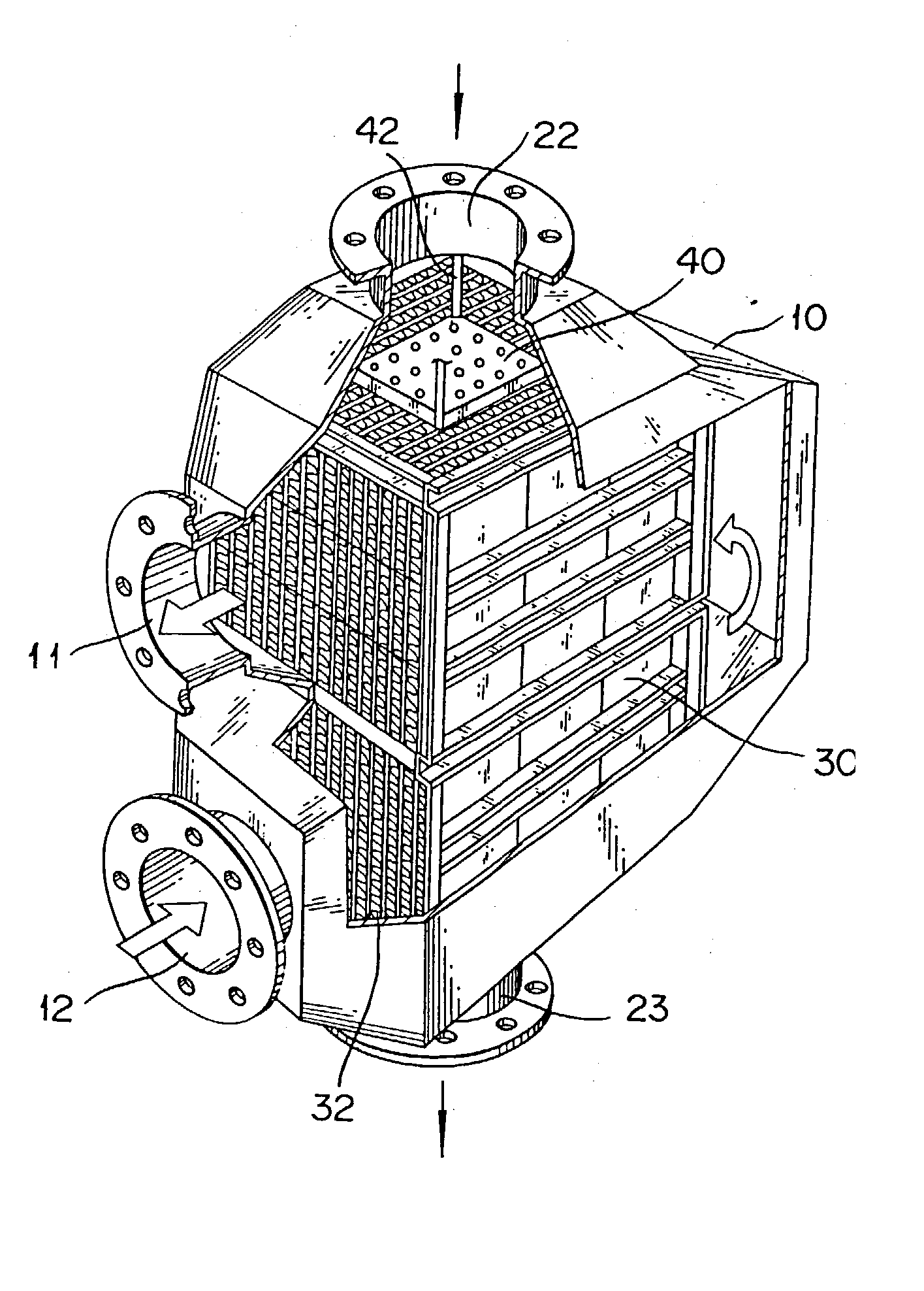
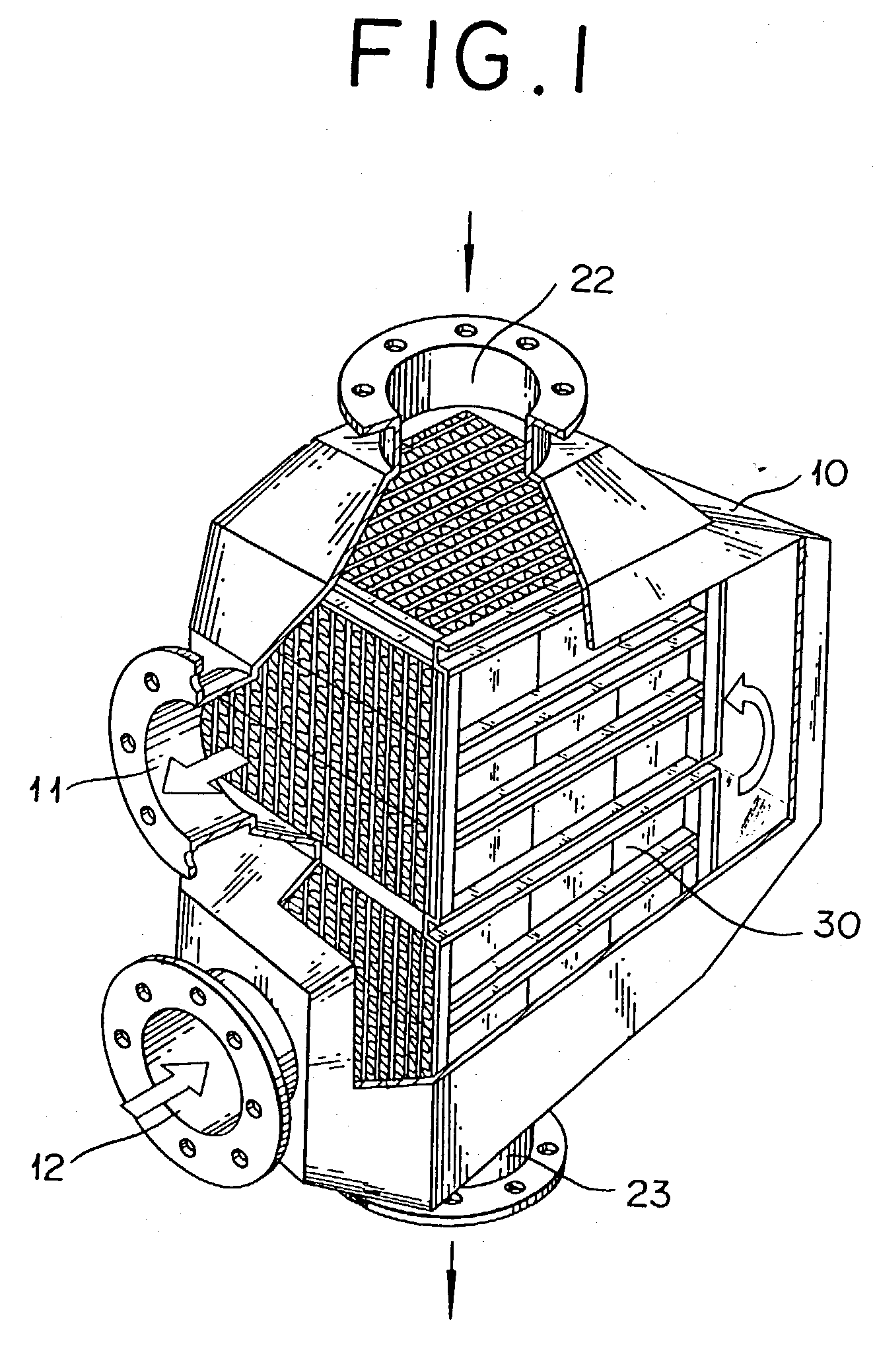
In an apparatus provided with a plate type heat exchanger as a heater and / or a cooler and operated to treat a gas containing an easily blocking substance, a method for preventing the plate type heat exchanger from being blocked is disclosed which is characterized by i) setting the width of a flow path on a plate of the plate type heat exchanger in the apparatus in a range of 6-25 mm and ii) setting the average flow rate of the gas passing the plate type heat exchanger in the apparatus per unit cross-sectional area of the flow path on the plate in the range of 3-15 m / s. In the exchange of heat of an easily blocking substance by the use of a plate type heat exchanger, a method for preventing the plate type heat exchanger from blockage is disclosed which has the plate type heat exchanger provided in the port for introducing a gas containing an easily blocking substance with a gas dispersion plate. This invention, in the heat exchange of an effluent gas emanating from a process for the production of (meth)acrylic acid or an ester thereof or the disposal of the gas, significantly allays blockage of the interior of the plate type heat exchanger.
Description
[0001] 1. Field of the Invention[0002] This invention relates to a method for preventing a plate type heat exchanger from blockage, and more particularly to a method for preventing a plate type heat exchanger used in an apparatus for disposal of discharge gas from blockage.[0003] 2. Description of the Related Art[0004] The heat exchanger for effecting transfer of heat between two fluids, one having a high temperature and the other a low temperature is one of the chemical machines which are used copiously in the chemical industry. The principle of the heat exchanger resides in exchange of heat between a fluid of a high temperature and a fluid of a low temperature through the heating surface.[0005] Generally, the heat exchanger effects the exchange of heat by introducing a fluid aimed at exchanging heat and by cooling or heating into a heat exchange part in the apparatus. The heat exchange part is known that there are various types such as the shell-and-tube type which has a multiplic...
Claims
Login to View More Application Information
Patent Timeline
 Patent Type & AuthorityApplications(United States)
IPC IPC(8): B01J19/00F28D7/16F28D9/00F28F19/00F28F27/02
CPCB01J19/002B01J2219/00252F28D7/1607F28F19/00F28D9/0062F28D9/0068F28F9/0278F28D7/1623F28F2250/102
InventorHIRAO, HARUNORIMATSUMOTO, YUKIHIRONAKAHARA, SEIDODO, OSAMUMITSUMOTO, TETSUJINISHIMURA, TAKESHISAKAMOTO, KAZUHIKOIWATO, HIROO
OwnerNIPPON SHOKUBAI CO LTD