Method of producing a high gloss coating on a printed surface

a printing surface and high gloss technology, applied in the direction of superimposed coating process, liquid/solution decomposition chemical coating, lithography, etc., can solve the problems of affecting the quality of printed materials, etc., to achieve rapid solvent evaporation, good flexibility, and good porosity

Inactive Publication Date: 2003-06-19
FRAZZITTA JOSEPH +1
View PDF0 Cites 40 Cited by
  • Summary
  • Abstract
  • Description
  • Claims
  • Application Information

AI Technical Summary

Benefits of technology

[0011] It is an additional object of the present invention to provide in at least one aspect an economical method of producing high gloss coatings on inked or ink-free surfaces using traditional printing processes.
[0012] It is yet another object of the present invention to provide in at least one aspect, a method for producing a high gloss coating which utilizes aqueous coating composition containing a substantial absence of volatile organic compounds or VOC's onto an ink or ink-free substrate in numerous printing processes.

Problems solved by technology

The prior art printing methods which utilize aqueous coatings are disadvantaged in the gloss values which can be obtained.
These methods suffer from the disadvantage that the coating must be cured upon deposition, creating time constraints in manufacturing with a resulting compromise in productivity.
In addition, the monomers which are used in these applications to create coatings tend to be hazardous and raise serious health and environmental issues in their continued use.
In addition to other negatives, these methods are often very costly compared to aqueous coating methods.
In addition to inline single coating units, expensive methods such as inline double coating units are also offered by a numerous printing press manufacturers in an effort to achieve high end results from inline wet or dry trap printing methods.

Method used


Image

  • Method of producing a high gloss coating on a printed surface
  • Method of producing a high gloss coating on a printed surface
  • Method of producing a high gloss coating on a printed surface

Examples


Embodiment Construction

Preparation of an Aqueous Coating Composition for Use According to the Present Invention Aqueous Coating Composition #1

[0137] This experiment demonstrates the ability of an applied aqueous coating composition to effectively wet and level over the surface of a coating face substrate according to the present invention, a first step in assessing the feasibility of using that composition in a wet or dry trap coating and printing process.

2 H.sub.2O 18.0% Low molecular weight polymer resin solution 30.0% High molecular weight polymer emulsion 43.5% Surfactant-Wetting agent 3.0% Defoamer 0.5% Polyethylene wax emulsion 5.0% 100.0%

[0138] Low Molecular Weight Polymer

[0139] Solid acrylic resin flake 98% non-volatile--Joncryl 684 manufactured by SC Johnson Polymer Note: The low molecular weight polymer is employed with other components for formulating a resin solution employed in the said coating composition.

3 Joncryl 684 55.0% Aqua Ammonia (28%) 7.5% Isopropyl Alcohol 5.0% Water 32.5% 100.0%

[0...


PUM

PropertyMeasurementUnit
smoothness Raaaaaaaaaaa

Abstract

The present invention is directed to a method for producing a high gloss coating on a printed surface. In the present method, an aqueous coating composition is deposited onto a surface to be printed using a blanket roller coating face which is a low energy, non-stick, smooth surface profile. In the present method, simultaneous with the deposition of aqueous coating onto a substrate, or shortly thereafter, pressure either alone or in combination with heat may be applied to the coating in order to create a substantially tack-free surface conforming to the surface of the coating face. By using a highly polished coating face, high gloss coatings may be readily obtained using this methodology in a number of traditional printing techniques including wet trap inline sheet-fed printing, heat-set offset printing, dry trap inline flexographic printing, offset web-fed printing and gravure printing. Coatings which are produced utilizing the present invention have high gloss values heretofore unobtainable using aqueous coating compositions.

Description

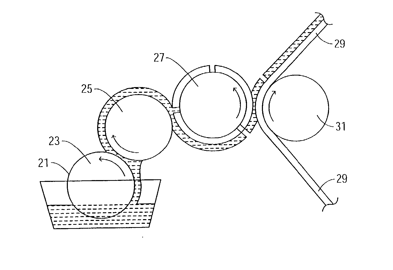
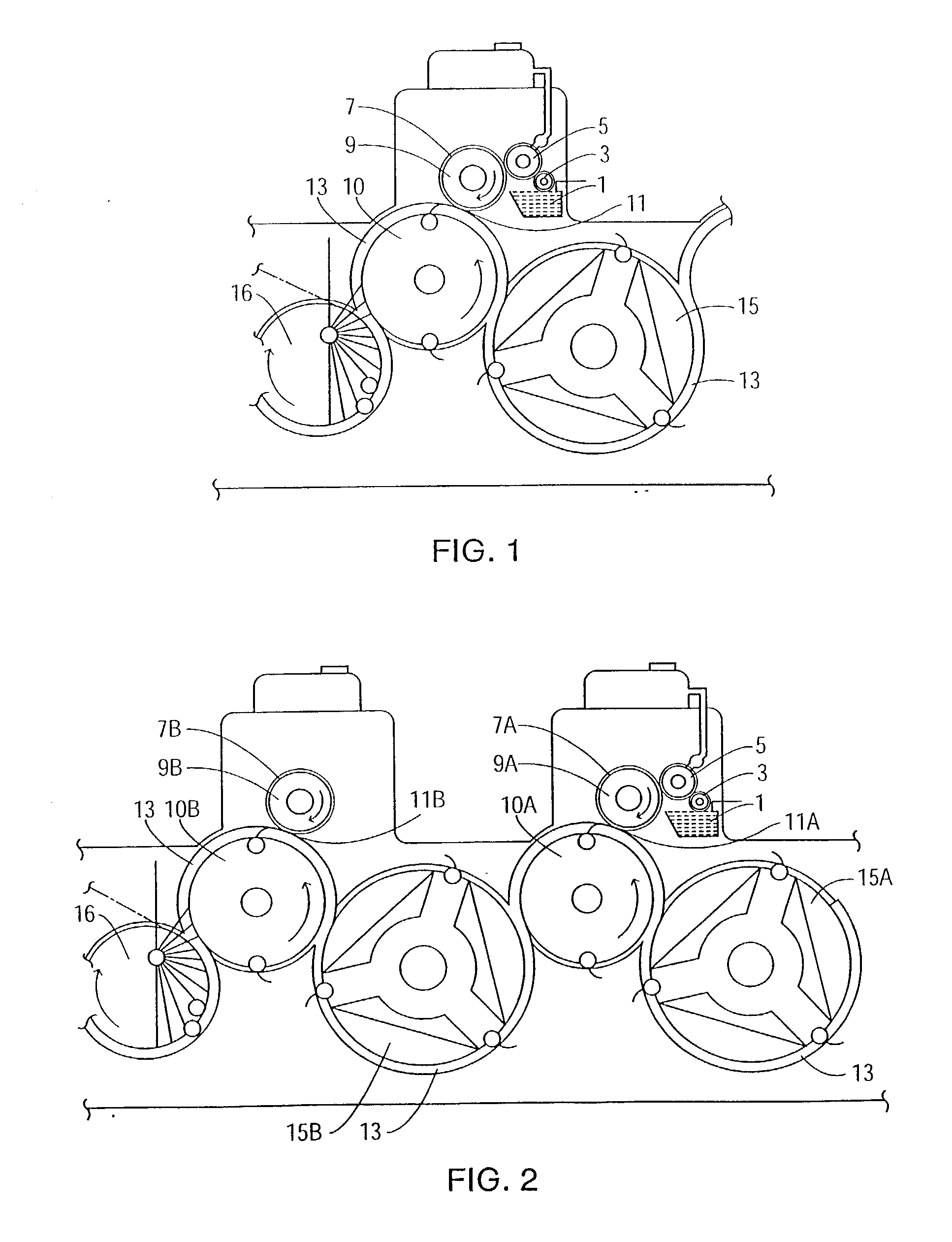
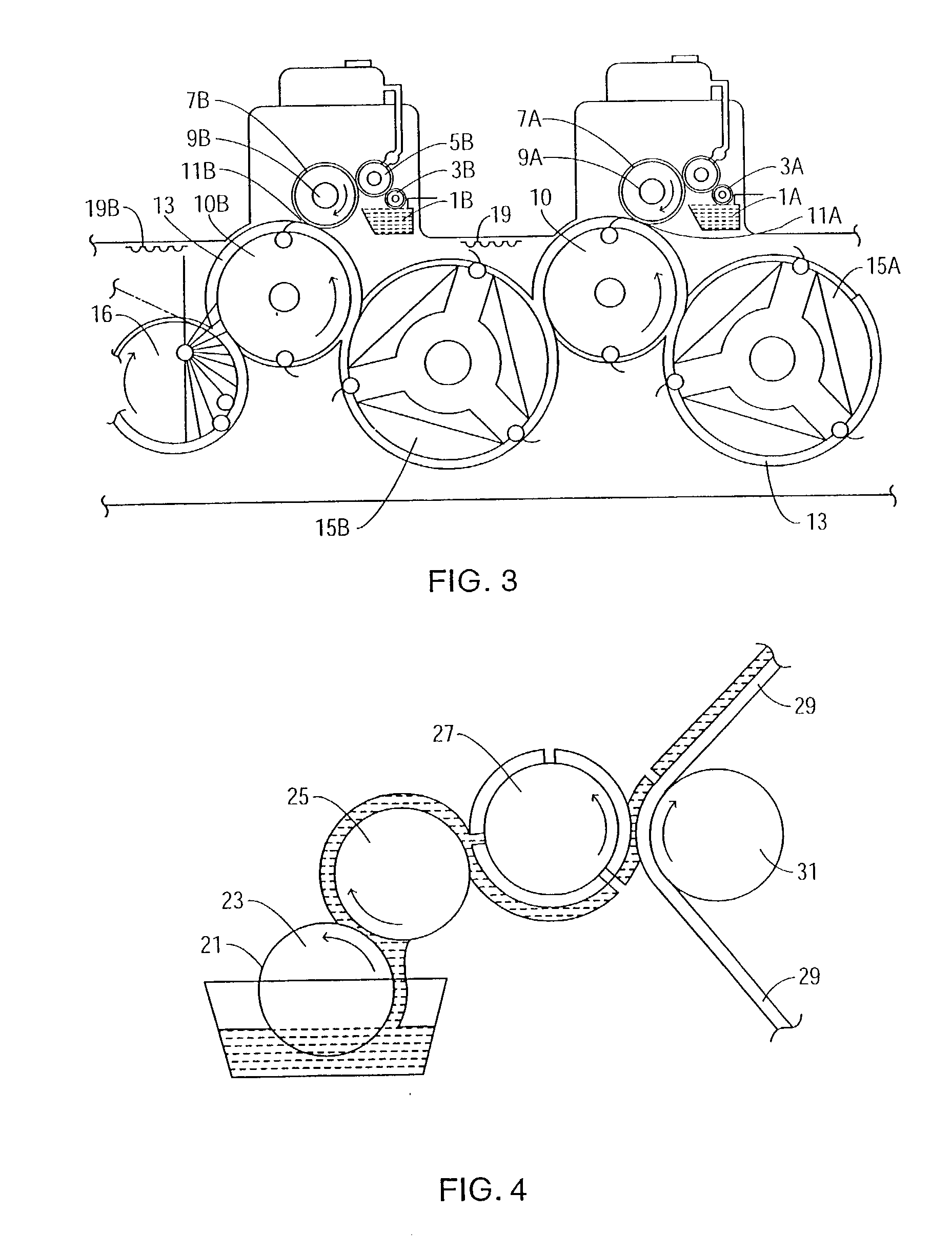
[0001] The present invention relates to a novel method for the deposition of an aqueous coating composition in a traditional printing process including, for example, traditional printing techniques such as wet trap inline sheet-fed printing, web-fed offset printing, dry trap priting processes including dry trap inline flexographic printing, offset web-fed printing, and gravure printing. Methods according to the present invention rely on the application of pressure, and in certain instances, temperature above ambient, to the aqueous coating composition produces a coating film surface which substantially conforms to the surface of the coating face. The result is a method which produces exceptionally high-gloss coatings from standard aqueous coating compositions.[0002] Use of the present invention allows a standard aqueous coating composition to be deposited onto a printing surface in virtually any printing process with the resulting coating producing a high gloss finish not otherwise ...

Claims


Application Information

Patent Timeline
Patent Type & Authority Applications(United States)
IPC IPC(8): B41M7/02B05D1/28B05D3/02B05D3/06B05D5/02B05D7/00B41F7/32B41M7/00
CPCB05D1/28B05D3/0254B05D3/067B05D5/02B05D7/542B41M7/0054B05D2203/22B41F7/32B41P2235/31B41M7/0045B05D7/544
Inventor FRAZZITTA, JOSEPHFRAZZITTA, FRANK V.
Owner FRAZZITTA JOSEPH
Why Eureka
Try Eureka