
Multiple Station HVLP Spray Coating System Utilizing a Rotary Vane Pump and Manifold Design with a Control System Function

a control system and spray coating technology, applied in the direction of liquid transfer devices, machines/engines, liquid fuel engines, etc., can solve the problems of high coating cost, inability to use air they pumps for atomizing coatings or fresh air breathing without adding costly filters and regular maintenance, heat and inefficiency, etc., to increase the number of spray stations, increase the speed and coverage of the delivery, and improve the effect of cost efficiency

Active Publication Date: 2015-08-13
APOLLO SPRAYERS INT
View PDF5 Cites 2 Cited by
  • Summary
  • Abstract
  • Description
  • Claims
  • Application Information

AI Technical Summary

Benefits of technology

The present invention provides a system that allows a rotary vane type pump to be attached to a manifold and regulator assembly to meet the air pressure requirements of the HVLP coating process and provide enough volume to atomize high solid type coatings. This system can be used for a wider variety of applications, increase the number of spray stations, speed and coverage of the delivery, and overall transfer efficiency in the coating process, resulting in higher uniformity of coatings, reduced wasted material and labor costs, and increased speed in application.

Problems solved by technology

The air they pump cannot be used for atomizing coatings or for fresh air breathing without adding costly filters and regular maintenance.
Unfortunately stacking these individual turbine elements creates inherent heat and inefficiencies and the practical maximum any manufacturer has been able to achieve to date in output pressure is around 7 PSI, or 30% below the allowable and optimum HVLP pressure allowed.
Not having the maximum 10 PSI allowed at the Spray gun tip limits the amount of coating that can be applied per hour (or throughput) so even though transfer efficiency is increased so is the application times leading to higher coating costs.
Unfortunately, most present day HVLP systems are able to atomize only low solid coating formulations so their application and value is limited to only a small part of the coating business.
The stacked pancake style HVLP turbine is limited in volume and therefore no extra air is available to supply breathing systems.
They have the disadvantages of having a short operational life and are noisy, but their greatest limitation is not having the capability to deliver the necessary 10 PSI air pressure required for most industrial HVLP applications and having enough volume to atomize high solid coatings.
Another disadvantage is that they heat the air that is compressed causing heat curing, a premature chemical reaction within the coating as it is applied which affects the finish.
Convention HVLP turbines do not have the capacity to atomize many of these formulations.
Because of these and other technical drawbacks, the HVLP field of coating applications today has been restricted to smaller project painting of limited sized objects with coatings of low solid content (easy to atomize).
The throughput of the current HVLP paint systems or the amount of paint that can be delivered per a given timeframe is small compared to other Systems so for many coating applications, HVLP has no practical or economical use despite the fact that it has much higher transfer efficiency.
Current technology requires spray operators to carry their own air supply in these situations which consists of tanks strapped on their backs, limiting range and motion of the operator as well as causing operator fatigue.
Typically, most HVLP spray systems utilize a gun that contains a cup reservoir that must be re-filled many times during the operation, causing time consuming delays and labor inefficiencies.

Method used


Image

  • Multiple Station HVLP Spray Coating System Utilizing a Rotary Vane Pump and Manifold Design with a Control System Function
  • Multiple Station HVLP Spray Coating System Utilizing a Rotary Vane Pump and Manifold Design with a Control System Function
  • Multiple Station HVLP Spray Coating System Utilizing a Rotary Vane Pump and Manifold Design with a Control System Function

Examples


Embodiment Construction

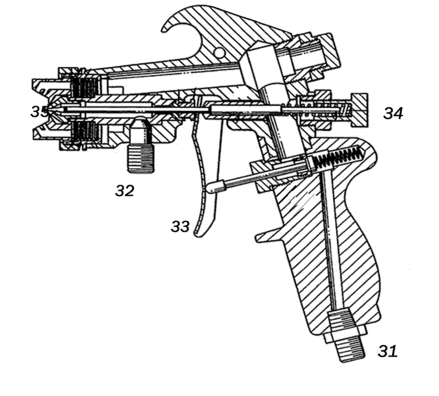
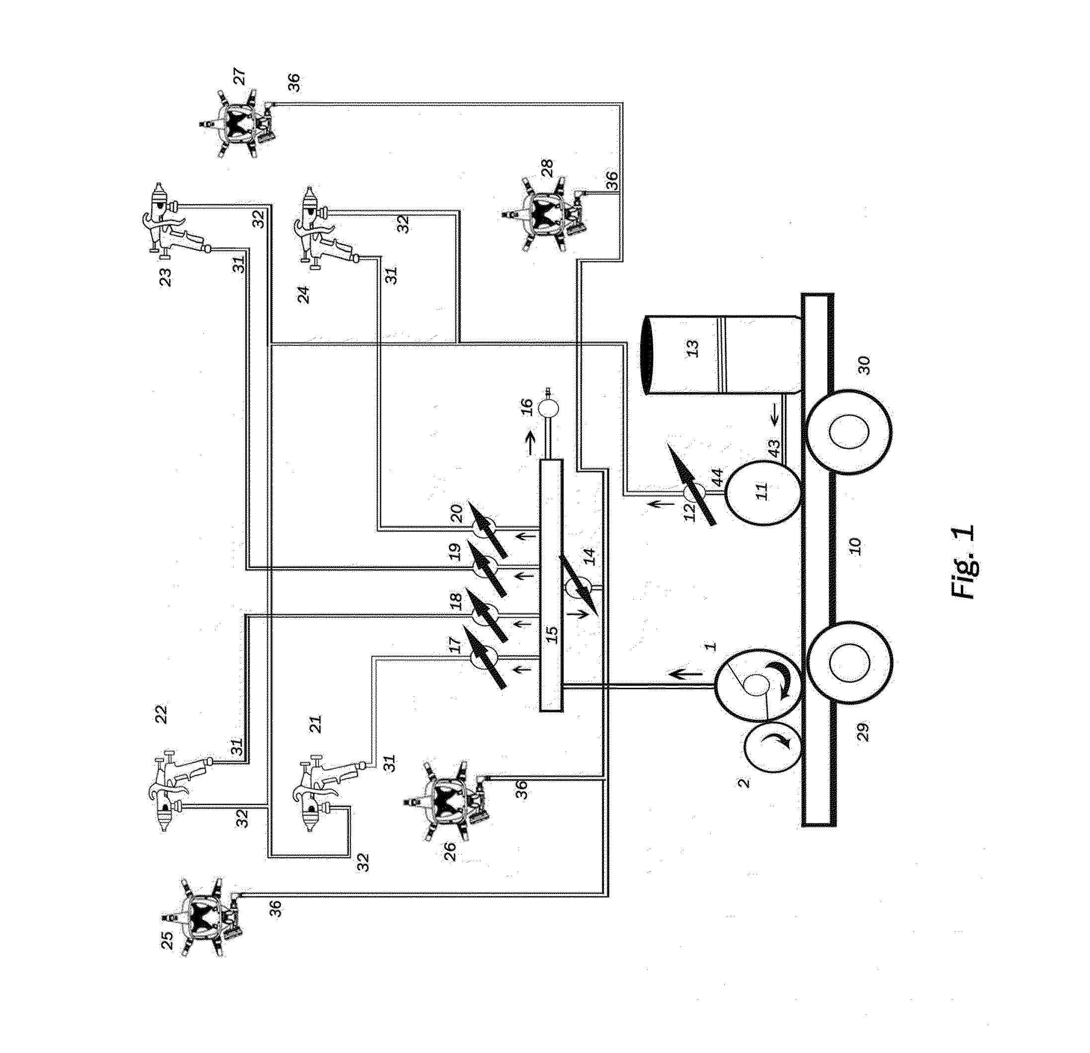
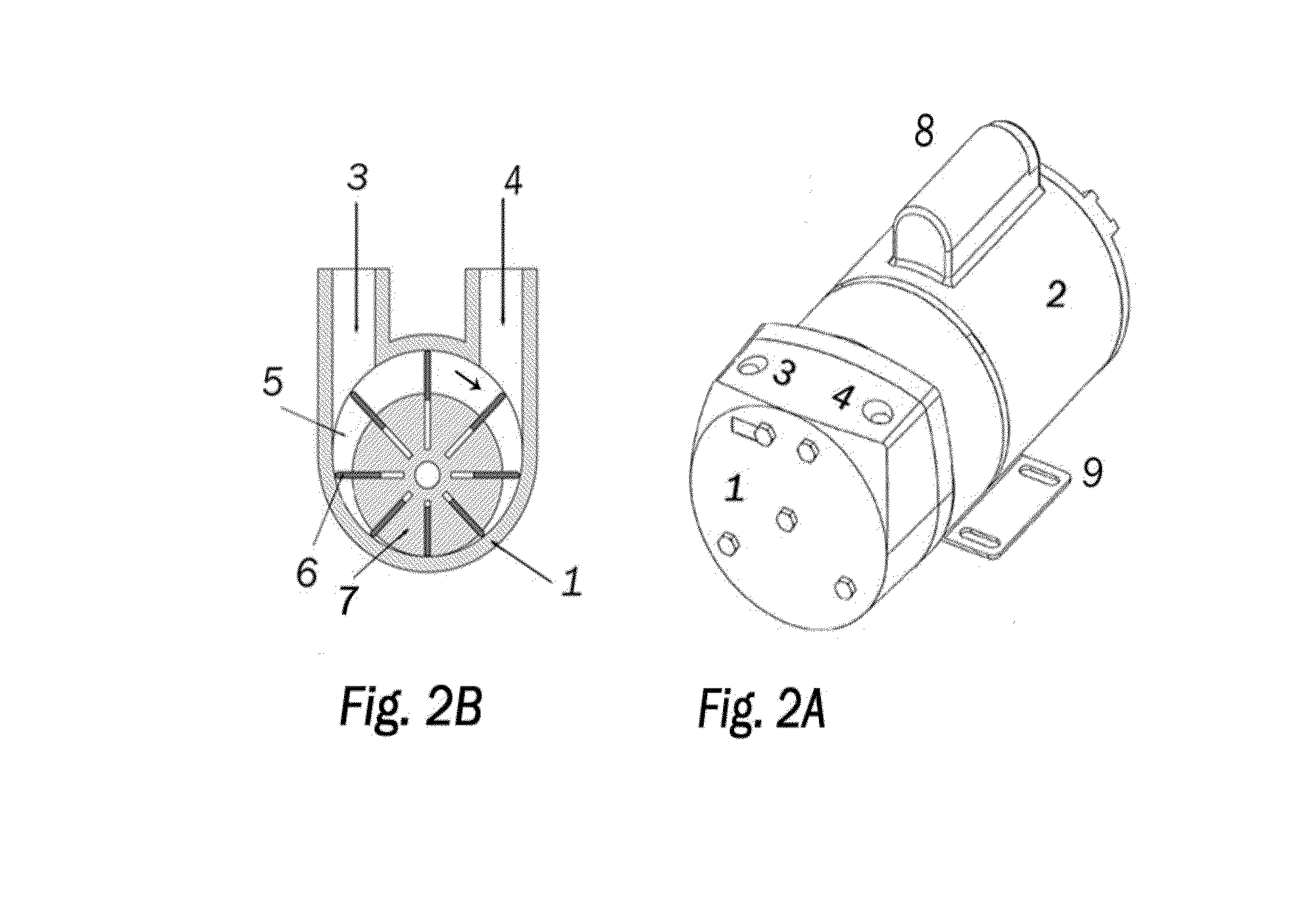
[0018]One preferred embodiment of the present invention is shown in FIG. 1. The center of the design is the rotary vane pump 1, powered by an electric motor 2 that provides air to the manifold 15. The manifold is the center of the present invention where air from above source is distributed to both the HVLP spray guns, 21, 22, 23 and 24, along with the fresh air operator breathing apparatus 25, 26, 27. 28. Air to each of the four spray guns is individually regulated by regulators 17, 18, 19, and 20 and connect at each of the four guns at 31, the air input side of the spray guns. Individual air regulators allow losses in each line to be different due to hose length, type of gun, atomization rate, etc where each regulator can be adjusted to compensate. Air pressure regulator 14 regulates manifold pressure to each of the fresh air operator breathing apparatuses sourced at 36 and each breathing mask has its own adjustment, item 37 of FIG. 4. The gun air regulators will adjust the air wi...


PUM


Abstract

A high volume low pressure (HVLP) coating application system employing a rotary vane pump and manifold assembly that provides an improved source of air for increased spray gun atomization of high solid coatings and faster applications of more even coated surfaces with continuous HVLP pressures of 10 PSI at the spray gun output and the ability to power multiple spray guns and breathing apparatus from a single manifold system.

Description

1. FIELD OF THE INVENTION[0001]The present invention relates to the field of coating delivery systems that are used in commercial applications to deliver paint and other liquids to surfaces requiring coatings for protection, enhancement, product coloring or texture and for multiple other reasons. There are many coating delivery technologies that have developed and are used in the field. The coatings field can be broken down by industry categories that use specific coating delivery technologies based on application, types of coatings and economy of delivery. Architectural coatings for building and structures require a different type of delivery system than does automotive or aircraft finishes. For coating buildings, the primary concern is the speed of delivery and getting a complete and heavy coating, whereas in automotive coating the focus is precision and control with attention to detail in getting a thin, even coat and adding multiple layers to achieve durability with a consistent...

Claims


Application Information

Patent Timeline
Patent Type & Authority Applications(United States)
IPC IPC(8): B05B7/24A62B18/02F04C13/00A62B23/02A62B7/10F04C2/344B05B15/00A62B18/08
CPCA62B18/02A62B18/084A62B23/025A62B7/10B05B15/00F04C13/002B05B7/2464B05B7/2486F04C2/344A62B7/12B05B7/2491F01C13/02F04C14/24
Inventor ROIDE, PAUL ANTHONY
Owner APOLLO SPRAYERS INT
Learn More