Forming and modifying dielectrically-engineered microparticles

a technology of dielectric engineering and microparticles, applied in the field of forming and modifying dielectrically engineered microparticles, can solve the problems of not allowing for a method whereby analytes may be indexed, detected, and manipulated, and not allowing for the separate manipulation of many different types of analytes

Inactive Publication Date: 2003-06-26
BOARD OF RGT THE UNIV OF TEXAS SYST
View PDF70 Cites 189 Cited by
  • Summary
  • Abstract
  • Description
  • Claims
  • Application Information

AI Technical Summary

Problems solved by technology

Although these improvements have exhibited degrees of success in the field, problems remain.
Notably, these methods still do not allow for a method whereby analytes may be indexed, detected, and manipulated at once, nor do they allow for the separate manipulation of many different types of analytes at once.
Unfortunately, this process may be somewhat complicated and time-consuming.
Manipulation protocols based on microparticle labels unfortunately require additional analysis steps to identify the target analyte.
Although the above microparticle-based systems have exhibited at least a degree of utility in this field, the necessary additional steps of identifying a target (apart from manipulating the target) represent extra time and cost to the scientist or engineer.
Further, even with the use of microparticles, it is sometimes the case that the detection of the microparticle itself does not necessarily infer the presence of the target analyte.
Still further, traditional microparticles do not allow for the simultaneous, separate manipulation of many different types of analytes.
Simply put, traditional microparticles do not allow for the indexing of different analytes followed by simultaneous manipulation, detection, and / or identification.
In other words, traditional techniques do not allow for the creation of a library of different probes that may each bind to different targets and allow for simultaneous manipulation, identification, and detection of the different species.

Method used


Image

  • Forming and modifying dielectrically-engineered microparticles
  • Forming and modifying dielectrically-engineered microparticles
  • Forming and modifying dielectrically-engineered microparticles

Examples


example 1

Engineered Microparticle Design Considerations

[0208] Life science research typically requires analysis of particles that range in size from about 100 nm to 10 .mu.m in diameter. The main forces acting on particles in this size range are sedimentation forces and randomizing forces due to Brownian motion. For a particle of radius 1 .mu.m and density of 1.05 g / cm.sup.3 suspended in aqueous medium (.rho.=1.00 g / cm.sup.3) at 25.degree. C. the sedimentation and Brownian forces each have magnitude of approximately 2.times.10.sup.-15 N.

[0209] To effectively use conventional dielectrophoresis as a manipulating force, the cDEP force must be greater than the other forces acting on the particle, and in one embodiment, about an order of magnitude greater than the other forces acting on the particle. According to Eq. 4, if Re(f.sub.CM)=0.5, then .gradient.E(rms).sup.2 should be approximately 9.times.10.sup.12V.sup.2 / m.sup.3 to give a cDEP force that is ten times greater than the sedimentation or ...

example 2

Experimental Studies

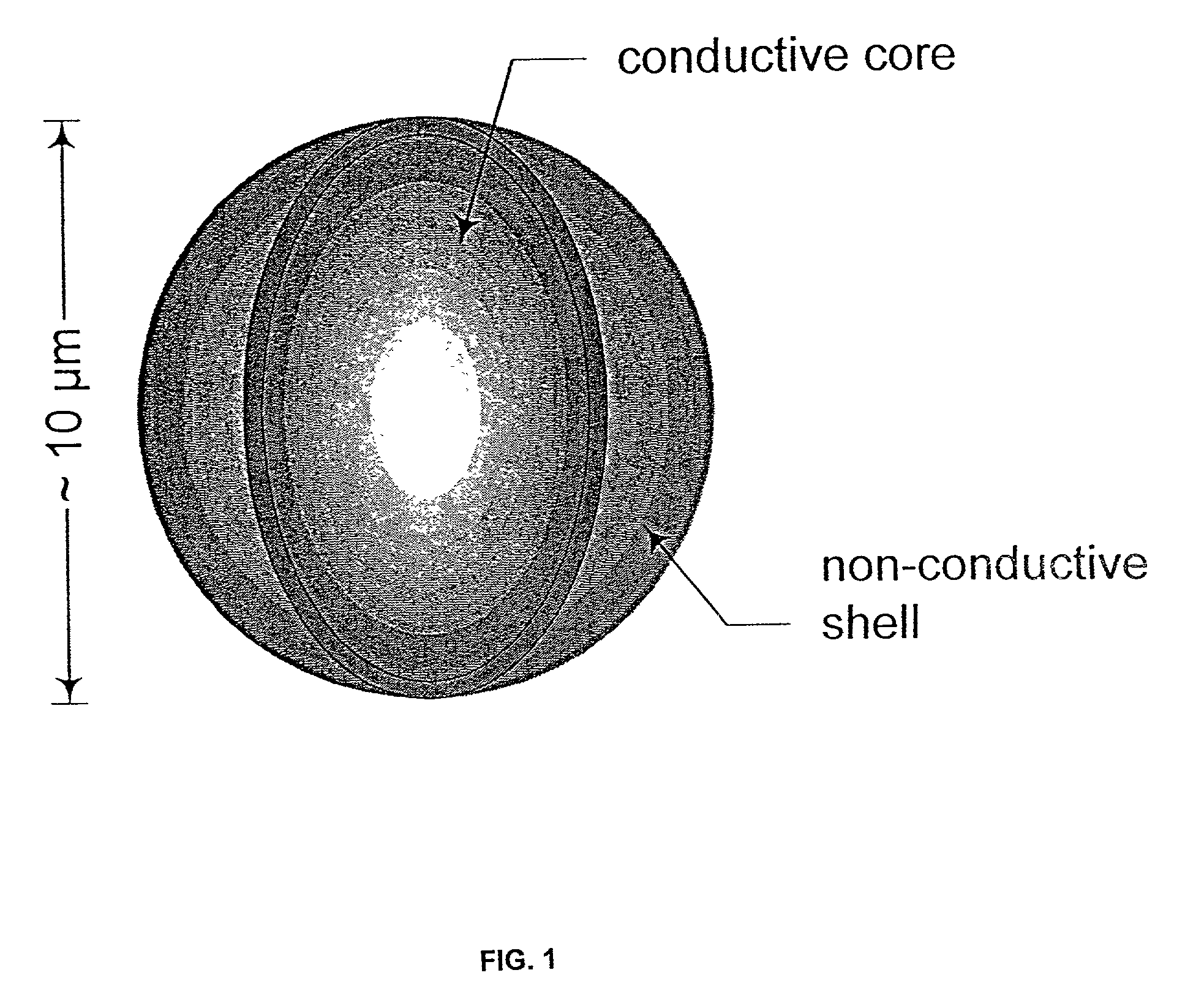
[0223] Silver-coated, hollow glass spheres were obtained from Potters Industries (Valley Forge, Pa.) and custom encapsulated in varying thicknesses of polystyrene by Theis Technology (St. Louis, Mo.) using a surfactant-free microencapsulation protocol. The resulting microparticle structure was similar to that depicted in FIG. 1. Upon application of an inhomogeneous electric field from a castellated, interdigitated electrode array, microparticle manipulation was accomplished by switching the field frequency and voltage. Dielectric responses varied in accordance with the predictions of Eqs. 4 and 7. The results confirm the analysis presented here and indicate that both the dielectric and conductive properties of the polystyrene coating define microparticle behavior as expected. Experiments using dielectric ferrite microparticles from Dynal, Inc. (Lake Success, N.Y.) also confirmed that magnetic and DEP forces may be used simultaneously for microparticle manipulatio...

example 3

Applications of Engineered Microparticle Technology

[0224] The utility of microparticle-based technologies for the identification, manipulation and isolation of target cells is universal. Recently, the use of microparticles in molecular biology has become widespread and promises to redefine the methodologies employed in life sciences studies wherever cell or molecular targeting or recognition is required. Yet current approaches are one-dimensional and offer little flexibility. For instance, parallel probing of multiple targets is not possible, targets may only be attracted to a collection site so that negative selection (the preference in some sorting applications) is difficult if not impossible, and sorting is essentially digital (targets cannot be discriminated according to binding efficiencies but only according to whether or not they bind any number of microparticles ranging from one to tens of thousands). The methods described here overcome these limitations and offer the potent...


PUM

PropertyMeasurementUnit
radiusaaaaaaaaaa
conductivityaaaaaaaaaa
thicknessaaaaaaaaaa

Abstract

Engineered microparticles, libraries of microparticles, and methods relating thereto. The microparticles are distinguishable based on differences in dielectric response to an applied electric field. In different embodiments, the dielectric differences may be engineered through, but not limited to, dielectrically dispersive materials, surface charge, and / or fluorescence. Gangliosides may be incorporated with the microparticles to control aggregation. Vesicles including erythrocyte ghosts may be used as a basis for microparticles. The microparticles may utilize a biotin streptavidin system for surface functionalization.

Description

[0001] Methodology of the current disclosure may be used with the apparatuses and methods described in U.S. Pat. No. 6,294,063, which is expressly incorporated herein by reference.[0002] Other patents and applications that may be used in conjunction with the current disclosure include U.S. Pat. No. 5,858,192, entitled "Method and apparatus for manipulation using spiral electrodes," filed Oct. 18, 1996 and issued Jan. 12, 1999; U.S. Pat. No. 5,888,370 entitled "Method and apparatus for fractionation using generalized dielectrophoresis and field flow fractionation," filed Feb. 23, 1996 and issued Mar. 30, 1999; U.S. Pat. No. 5,993,630 entitled "Method and apparatus for fractionation using conventional dielectrophoresis and field flow fractionation," filed Jan. 31, 1996 and issued Nov. 30, 1999; U.S. Pat. No. 5,993,632 entitled "Method and apparatus for fractionation using generalized dielectrophoresis and field flow fractionation," filed Feb. 1, 1999 and issued Nov. 30, 1999; U.S. pat...

Claims


Application Information

Patent Timeline
Patent Type & Authority Applications(United States)
IPC IPC(8): C12N5/08C12N15/09C12Q1/68G01N33/53G01N33/543G01N33/555
CPCG01N33/54373B82Y30/00
Inventor GASCOYNE, PETER R.C.VYKOUKAL, JODYVYKOUKAL, DAYNENESHARMA, SUSANBECKER, FREDERICK F.
Owner BOARD OF RGT THE UNIV OF TEXAS SYST
Why Eureka
Try Eureka