Reciprocating vane type rotary internal combustion engine (vane engine)

Inactive Publication Date: 2003-07-03
YOSIKANE IKITAKE
View PDF0 Cites 14 Cited by
  • Summary
  • Abstract
  • Description
  • Claims
  • Application Information

AI Technical Summary

Benefits of technology

0059] This invention is that the lubrication of vane tip in activation makes good, and gas bearing action force by wedge action at (a) part of combustion

Problems solved by technology

The reason that NSU Wankel rotary engine expected to bring a revolution to an engine was defeated, is thermal efficiency being low, for cooling area is too big to the exhaust volume, and it was fatal, though it is put to practical use an

Method used


Image

  • Reciprocating vane type rotary internal combustion engine (vane engine)
  • Reciprocating vane type rotary internal combustion engine (vane engine)
  • Reciprocating vane type rotary internal combustion engine (vane engine)

Examples


Example

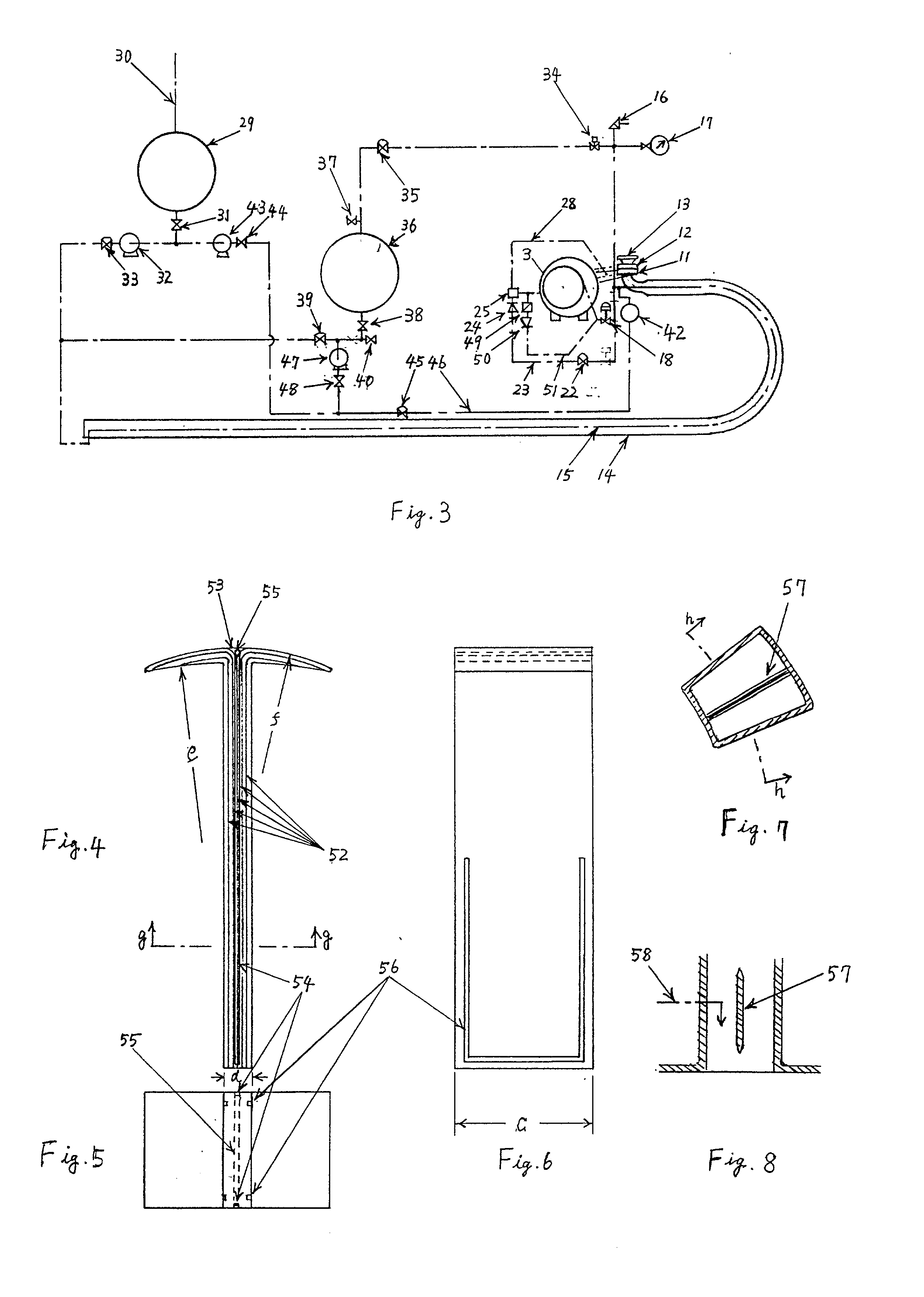
[0092] The production process of reciprocating vanes depending on this invention is explained with FIGS. 4.about.6 as follows.

[0093] At first, laminating the carbon fiber textile (52) which woven from thread bundled up several thousand of carbon single fiber of marketed 10 .mu.m size degree, till thickness becomes (d) with width (c) of vane, on intersection line of plane of half of the thickness and plane include tip lines of both guides plane on the state in top dead point, divide it in two and bend to an other side mutually at an angle of 90.degree. around the tip line of both guide plane, and cut off tip of textile from small radius of curvature sequentially, and inside radius of curvature (e) becomes to between a rotor (1) radius and infinity, and outside radius of curvature (f) becomes into around 1 / 3 of rotor (1) radius, and all surface of this vane and dividing tip section (53) is soaked and broil hardened with graphite, carbonization silicon and so on as a matrix, and the ou...


PUM


Abstract

On the reciprocating bane of a reciprocating vane type rotary internal combustion engine (vane engine), big centrifugal force is generated by a high-speed rotation and is opposed to combustion pressure, and force equal to or more than seal action force to be necessary for vanes tip is added to the case inside, and friction loss becomes big. For get the force to support centrifugal force and to make this friction loss small, a vane tip cross-section vertical to a rotating axis is formed in a pick-shaped so as to generate gas bearing action force greatly. In addition, in order to raise a hydrostatic pressure in neighborhood of tangent line of both the outside curved surface of vanes tip and the case inside, and to get the multiplication effect that raise a hydrodynamic pressure in the vanes tip, gas supply hole is established parallel to the rotating axis in the midsection of the vanes tip. Therein, porous matrix or great many minute holes connect between the gas supply hole and outside curved surface of the vanes tip. High pressure air, combustion pressure gas or steam is provided to gas supply hole, then, it is spouting out from outside curved surface of it, and get a high hydrostatic pressure and raise a hydrodynamic pressure. Furthermore, because there is not the first steam for lubrication searing in a start, steam reservoir and pressurization pump is established. Therein, compress the air in the steam reservoir by press-fitting water in steam reservoir, then it is used to lubrication searing. After an engine began to move in start or activation, till pressure of revitalization vapor by exhaust becomes proper, as method to get the high pressure gas for lubrication searing, part of the combustion gas which is pulled out from the second steam supply-cum-combustion gas pulling out port, which established a little to the bottom dead point from the center point of the front side vane toward rotating, this vane which combustion chamber pressure of this engine, in which continued fuel injection and combustion (make the best use of characteristic of this engine), become maximum, is connected with the first steam supply pipe for lubrication searing through a filter and a check valve. Fuel injection in neighborhood of the top dead point is difficult to avoid the surface of a wall adhesion, because combustion chamber is so flat. As substitute for it, I devised a method to do vaporization of fuel or injection on the part which close late of air supply port near the bottom dead point, so as to vaporized or injected fuel mix with supply air without loss and so as not to join the air to pass without dropping in.

Description

[0001] This invention relates to improvement of a high pressure gas supply device for reciprocating vane and lubrication sealing of reciprocating vane type rotary internal combustion engine (the 961789 th Japan patent issue, Showa 42 Patent application 080957)BACKGROUND TECHNOLOGY[0002] For air pollution and global warming, exhaust matter (HC, CO, NOx, blacksmoke, SO.sub.2, CO.sub.2) from a motor for car and industry plays big role.[0003] So I aim at practical use of a reciprocating vane type rotary engine which has possibility to minimize the pollutant appearing from a motor and to maximize the thermal efficiency.[0004] The possibility that a reciprocating vane type rotary engine does a pollutant in minimum is to say that, this engine is suited for a high-speed rotation (more than 12000 rpm), there is possibility to restrain forming of NOx, by the combustion and expansion process is over before the forming reaction time required of NOx passes, and separating combustion gas forcibly...

Claims


Application Information

Patent Timeline
IPC IPC(8): F01C1/344F01C21/08F02B53/00
CPCF01C1/3441F01C1/3442F02B2053/005F02B53/00F01C21/0809
Inventor YOSIKANE, IKITAKE
Owner YOSIKANE IKITAKE
Why Eureka
Try Eureka