Imaging of microarrays using fiber optic exciter

a fiber optic exciter and microarray technology, applied in the field of microarray imaging, can solve the problems of affecting the efficiency of dichroic optical filter efficiency, affecting the detection and resolution of resulting images, and affecting the efficiency of the system with a common laser path,

Inactive Publication Date: 2003-07-10
BIO RAD LAB INC
View PDF4 Cites 13 Cited by
  • Summary
  • Abstract
  • Description
  • Claims
  • Application Information

AI Technical Summary

Problems solved by technology

This mechanism suffers limitations in sensitivity and in the level of detection and resolution of the resulting image.
Systems with a common laser path generally suffer from dichroic optical filter efficiency problems, since rejection of the very strong excitation light is accompanied by rejection of a substantial portion of the much weaker emission light.
Further inefficiencies arise from the laser scanning systems in these devices whic...

Method used


Image

  • Imaging of microarrays using fiber optic exciter
  • Imaging of microarrays using fiber optic exciter
  • Imaging of microarrays using fiber optic exciter

Examples


Embodiment Construction

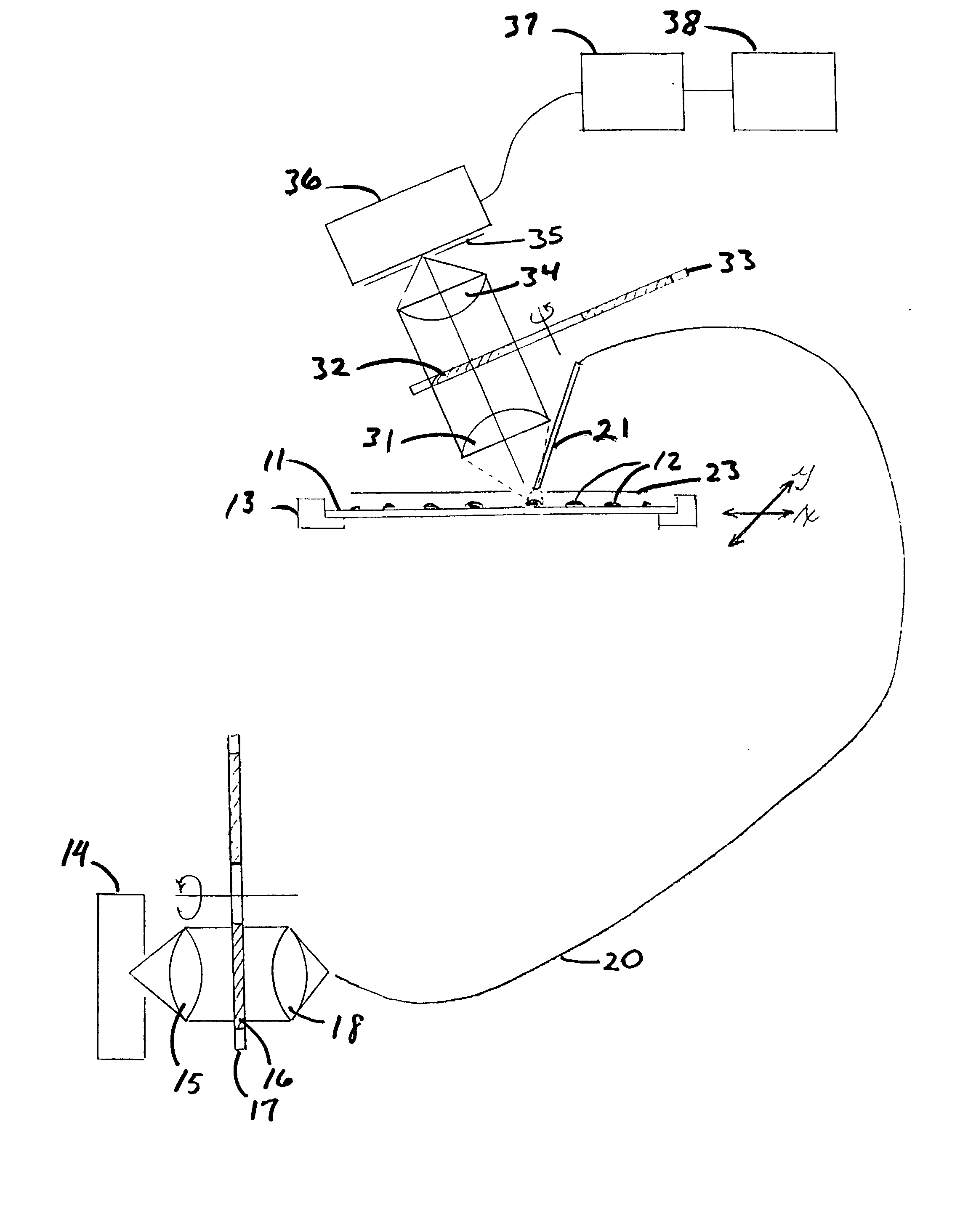
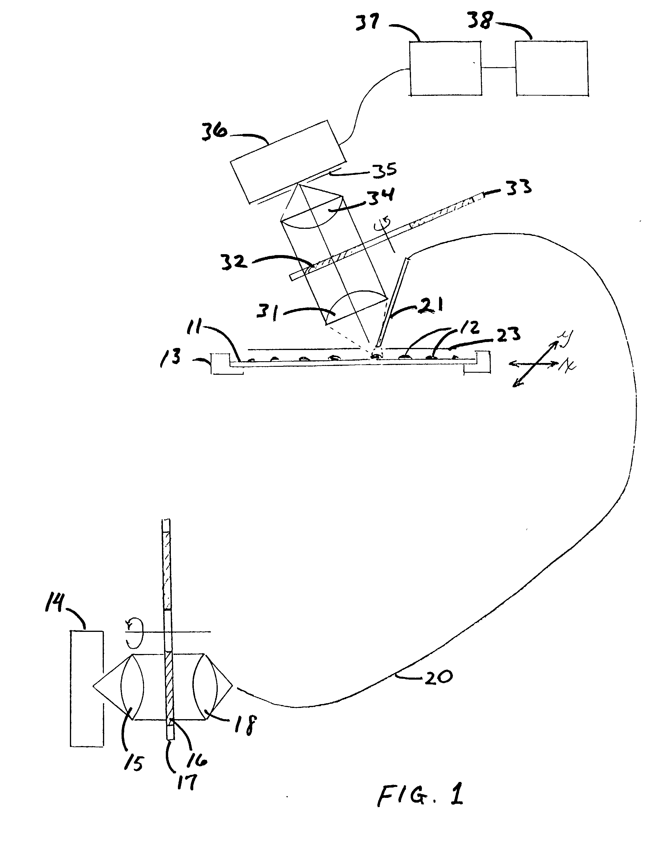
[0015] Microarrays are generally planar arrays, typically two-dimensional rectangular arrays, of microdots, referred to herein as "spots," each spot measuring at most 500 microns in diameter and containing a test specimen to be analyzed by chemical or biochemical assays for either diagnostic or screening purposes. The most common such specimens are nucleic acid segments, although biological species of various kinds have been used and can be used here as well. The spots in a microarray are processed in parallel in accordance with the analyses, the spots containing labels such as fluorophores to indicate the successful specimens. Microarrays of this type are typically deposited on a flat, inert, and often light-transmissive substrate such as a microscope slide. Other microscopic arrays include bio-chip ("lab-on-a-chip") technologies and electrophoresis sequencing readers that include microscale and / or nano-scale fluidic channels. Examples of microarray devices of this type are those a...


PUM


Abstract

Microarrays are imaged by an illumination and detection system that supplies excitation light through one or more optical fibers, each fiber transmitting excitation light from an excitation light source to a single spot in the microarray. Emission light from each spot is then collected by a collimating lens and converted to a signal that is compiled by conventional software into an image of the entire microarray. The optical fiber(s) and the collimating lens are arranged such that the direction of travel of the excitation light and the direction along which the emission light is collected are not coaxial, and preferably both are at an acute angle to the axis normal to the plane of the microarray.

Description

[0001] This application claims the benefits of co-pending U.S. provisional patent applications Nos. 60 / 325,855 and 60 / 325,968, both filed on Sep. 27, 2001, for all purposes legally capable of being served thereby. The contents of each of these provisional patent applications are incorporated herein by reference in their entirety, as are all other patent and literature references cited throughout this specification.[0002] 1. Field of the Invention[0003] This invention resides in the field of imaging of microarrays by optical excitation of materials in the arrays and detection of the emissions resulting from the excitation, and particularly in systems for conveying excitation light to microarrays.[0004] 2. Description of the Prior Art[0005] Numerous devices are commercially available for reading DNA microarrays as well as microarrays of other materials. Examples of these devices are the Chip Scanner technologies of Affymetrix, Inc., Santa Clara, Calif., USA, confocal laser scanners of...

Claims


Application Information

Patent Timeline
IPC IPC(8): G01N21/25G01N21/64H04N1/04
CPCG01N21/6452Y10T436/11G01N2021/6484
Inventor NAGHIEH, HARRY R.HILLENDAHL, JAMES W.WALDBESER, DAVID E.
Owner BIO RAD LAB INC
Why Eureka
Try Eureka