
Motility analysis, display, and interpretation system

a technology of display and interpretation system, applied in the field of medical diagnostic systems and methods, can solve the problems of large amount of health care resources consumed in diagnosis and management, large amount of health care resources, and inability to provide qualitative and often crude information

Inactive Publication Date: 2003-07-31
HOLMES HARLAN K +2
View PDF5 Cites 15 Cited by
  • Summary
  • Abstract
  • Description
  • Claims
  • Application Information

AI Technical Summary

Benefits of technology

[0012] Up to the present time, clinical studies alluded to herein have been conducted by experts in facilities conducting research or in facilities specializing in a particular physiological dysfunction, which obviated the need for more inclusive systems. Multiple sensors to adequately characterize the bodily structure of interest from a single forcing function and sufficiently powerful desk top computer systems and data acquisition capabilities to acquire, process and display the acquired data sequence in near real-time are now available. Adding built-in diagnostic routines to interpret the acquired data patterns and identify the most probable dysfunction, allows the present system to be utilized by less skilled practitioners. Obtaining, displaying, and interpreting a sufficiency of data in a minimum of time will minimize the discomfort to the patient, reduce the cost of patient care, and greatly increase the number of facilities where comparable investigations can be performed. Also, because the data is now in a standardized form, it is easily transmitted electronically to a specialist for additional consultation.

Problems solved by technology

The prevalence of these disorders is significant, and their diagnosis and management consumes a large amount of health care resources.
However, these diagnostic tests only provide qualitative and often crude information ultimately used to establish a proper diagnosis of motor dysfunction.
Despite the appeal of intraluminal manometry, currently available systems have important limitations.
The most important of these is that few recording sensors are used, the sensors are spaced such that spatial resolution is inadequate, and the resultant methods of analysis are inconsistent because of lack of sufficient data.
In the former systems, current intraluminal probes typically include no more than 4 sensors, severely limiting the amount of acquired pressure information.
Consequently, the present devices are considerably inadequate.
A system of this type presently is not available.
However, the demonstration of motor dysfunction is expectedly limited.
Water-perfused systems also suffer the limitations imposed by their sensitivity to gravity bias and the important technical burdens in maintaining the perfused catheters and pneumohydraulic pump apparatus.
The system requires meticulous cleaning and maintenance to provide accurate pressure data from repeated use, and the apparatus is cumbersome and poorly transportable.
Because of the limited circumferential extent, information regarding the luminar pressures at a location may be incomplete.
Additionally, electrical conductors must extend through the catheter system to each sensor element, creating a potential safety issue, as well as limiting the number of sensor elements because of the finite space available to route the many conductors through the central catheter lumen.
This ultimately limits the practical number of sensors that can be accommodated.
At the present time, interpretation of a given set of data may result in inconsistencies because of different medical training, experience, stress level, etc.
; or one physician's mental rules may be difficult to articulate and thus difficult to transfer to others; or where the patient's condition is overly complex and not well understood.

Method used


Image

  • Motility analysis, display, and interpretation system
  • Motility analysis, display, and interpretation system
  • Motility analysis, display, and interpretation system

Examples


Embodiment Construction

should be read together with the accompanying drawings, wherein:

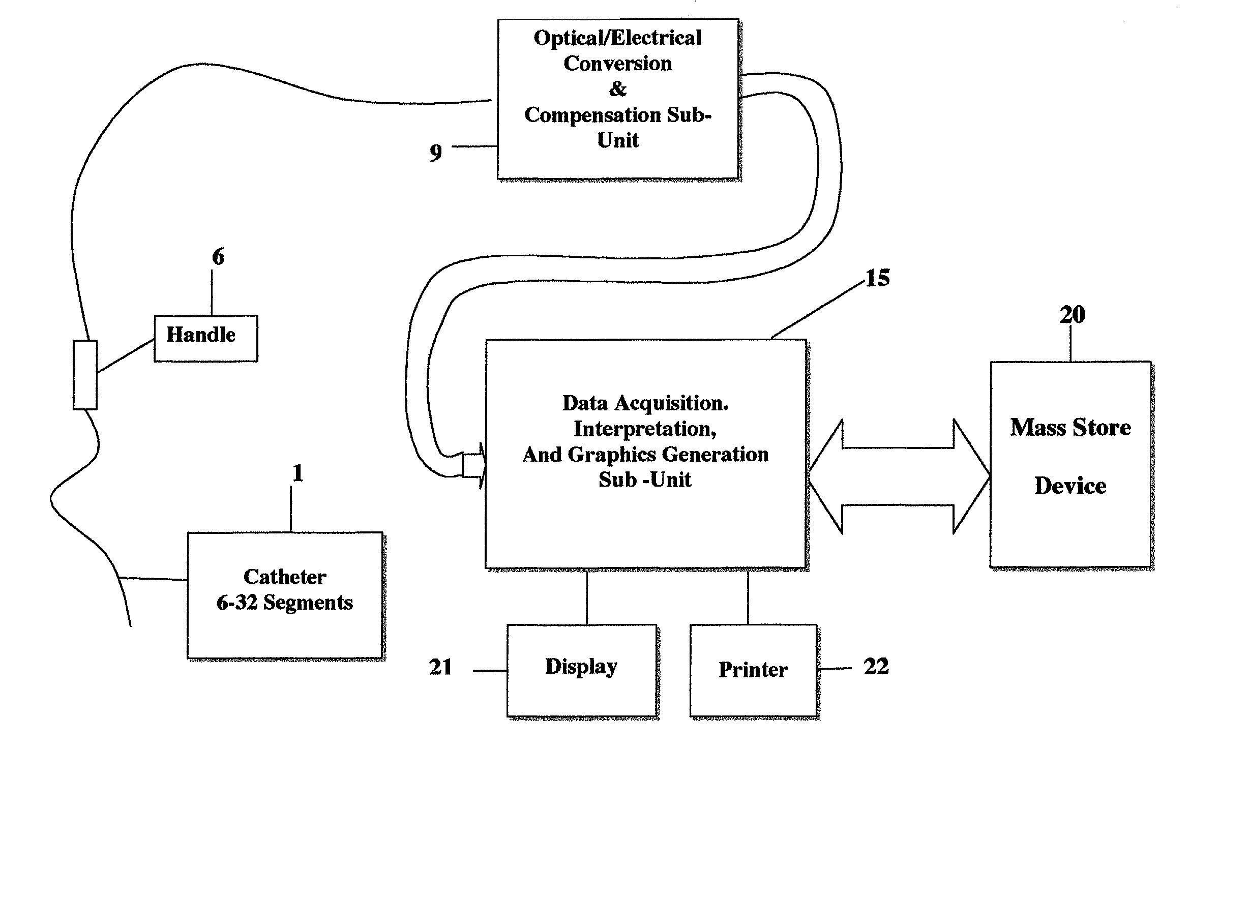
[0014] FIG. 1 is an overall schematic depicting the system according to the present invention;

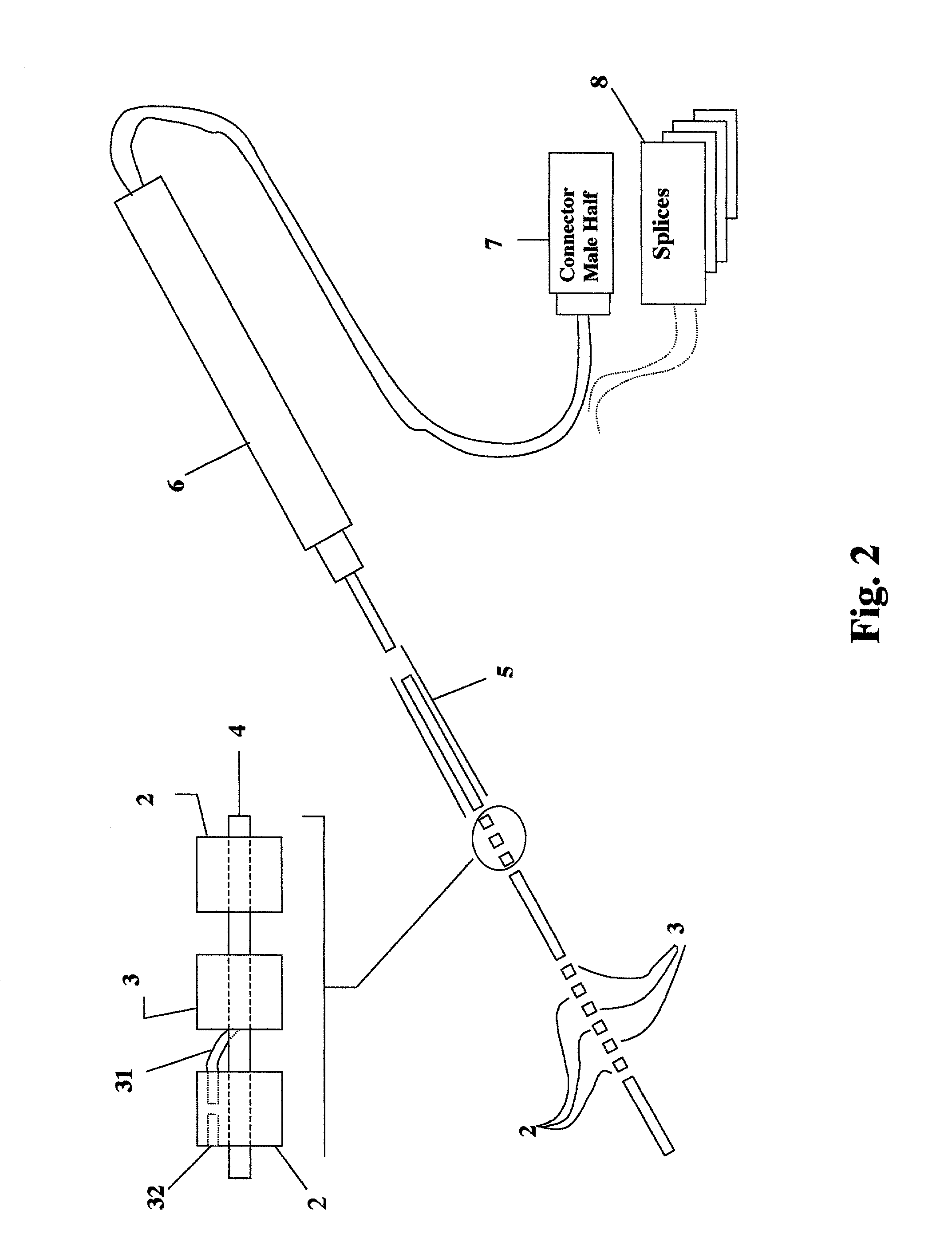
[0015] FIG. 2 is a schematic depicting the catheter sub-unit of the system according to the present invention;

[0016] FIG. 3 is a schematic depicting the signal-conditioning sub-unit of the system according to the present invention;

[0017] FIG. 4 is a schematic depicting the data acquisition, storage, graphics display and interpretation module of the system according to the present invention; and

[0018] FIG. 5 is a typical display graphic obtained by the system according to the present invention.

[0019] Referring now to the drawings, an overall depiction of a preferred embodiment, consisting of sub-units and modules, is represented in FIG. 1, which shows the spatial array of opto-mechanical transducer elements, 1; the electro-optical analog conversion and optical power compensation sub-unit, 9; the multiple channel data acquisition...


PUM


Abstract

The system includes an array of transducers that simultaneously senses multiple intralumenal pressures, a data acquisition module that acquires and stores samples of the measured pressures, software routines for signal analysis, a software module for multi-dimensional data display presentations, and a software module to perform pattern recognition on the acquired data set to identify potential maladies that may be indicated by the analysis. The transduction elements are cylindrical segments that deform according to the circumferential pressures encountered. Distributing a quantity of these sensor segments at desired locations along a flexible support structure and providing a flexible sheath over the entire length forms the sensor array. Measuring the sensor deformation provides an electrical analog of the pressure causing the deformation. Acquiring these measurements in a suitable data acquisition and processing unit, including a display, printing, and plotting capability, completes the hardware elements. Integrated software modules complete the system.

Description

[0001] 1. Field of the Invention[0002] This invention relates generally to medical diagnostic systems and methods. It relates particularly to a system and method for providing a probabilistic diagnosis of physiological dysfunction present in any of several tubular cavities within a living body.[0003] 2. Description of the Related Art[0004] Motility within tubular structures of the body typically is the result of a complex interaction of muscles and their neural control mechanisms. Motility disorders that most commonly reach clinical significance are the motility disorders of the gastrointestinal tract. The prevalence of these disorders is significant, and their diagnosis and management consumes a large amount of health care resources. A variety of methods have been employed to correctly diagnose the nature of motor dysfunction, including radiological, radionuclide, and endoscopic procedures. However, these diagnostic tests only provide qualitative and often crude information ultimat...

Claims


Application Information

Patent Timeline
Patent Type & Authority Applications(United States)
IPC IPC(8): A61B5/03
CPCA61B5/036A61B2562/043A61B2562/0247
Inventor HOLMES, HARLAN K.CLOUSE, RAY E.BELLINO, DOMENIC A.
Owner HOLMES HARLAN K
Learn More