Inline degassing apparatus

Inactive Publication Date: 2003-08-14
PYROTEK JAPAN +1
View PDF7 Cites 62 Cited by
  • Summary
  • Abstract
  • Description
  • Claims
  • Application Information

AI Technical Summary

Benefits of technology

[0044] As explained fully in the above, due to the arrangement of the heaters 21 at the lower portion of the degassing container in a manner that the heaters 21 are substantially entirely immersed in or contacted with the molten metal, an dross build-up onto the heaters 21 can be greatly reduced, resulting in a reduction in a chance of damage to the heaters 21.[0045] Furthermore, due to the cantilever fashioned and substantially horizontal arrangement of the heater 21 according to the present invention, an increased degree of uniformity in the pressure applied from the molten metal to the surface of the heater is obtained, on one hand, and, on the other hand, a un-uniformity of the temperature of the degassing apparatus is avoided, resulting in an increase in a thermal efficiency.[0046] Furthermore, due to the provision of a plurality of the baffle plates 22 extending vertically on the side wall 14B of the degassing container 14, a moderation of the swirl movement of the molten material is realized, so that a pressure applied to the heaters 21 is reduced, thereby prolonging service lives of the heater protecting tube and the heater assembly itself. Furthermore, the baffle plates 22 function to generate turbulences in the molten metal, thereby speeding up the separation of the solid dissolved gases as well as inclusions from the molten metal, thereby enhancing a performance of the degassing operation.[0047] Finally, according to the present invention, the cantilever fashioned heater at the bottom of the container is combined with the arrangement of the baffle plates above the heater, thereby providing a unique structure of degassing apparatus of an increased service life as well as an increased efficiency.

Problems solved by technology

Accordingly, a high quality after processing or working can only be achieved when a separating or removal of nonmetallic inclusions from the molten metal is done prior to the processing or working.
Furthermore, the existence of the inclusions attached to the gases may generate various defects in the product after subjected to a processing or working.
Thus, it is quite likely that desired casting temperature cannot be maintained and in the worst case a solidification of the molten metal may be commenced.
Otherwise, a solidification of the metal remained in the container is started, which make it difficult that the metal remained in the container is smoothly molten together with the newly introduced metal into the container.
However, the aforementioned burner 6 heats the molten metal 9 from the upper side and, therefore, a difficulty is inevitably encountered that a heat cannot be easy reached to the molten metal in the lower position of the degassing container 1.
In addition, this system is disadvantageous in that the flame of the burner promotes oxidation of the molten metal and an increased amount of the dross is generated.
By such an attachment of the dross, a removal of the heater through the heater insertion aperture at the rid becomes to be difficult.
However, such a removal of the dross causes the heater to be instantly subjected to an outside air of low temperature, resulting in a rapid drop in a local temperature at a portion of the heater corresponding to a location around the liquid-gas boundary in the container.
As a result, a highly increased thermal stress is generated in the heater, which frequently causes an outer protection tube to be damaged, which is made of relatively expensive ceramic material.
In addition, '402 patent is also disadvantageous in an increased labor cost, which is needed for scraping the dross.
Thus, a damage is likely generated not only in the heater protection tube but also in the heater assembly itself.
In this structure, the heater protection tube is inevitably subjected to great stress due to the swirl movement of the molten metal as generated by the operation of the rotary gas-diffusing device, resulting in a shortened service life of the heater protection tube, which makes the maintenance cost to be expensive.
Furthermore, a non-uniformity in the temperature inside the apparatus is likely generated, which is disadvantageous not only from the view point of temperature control precision but also from the view point of thermal efficiency.

Method used


Image

  • Inline degassing apparatus
  • Inline degassing apparatus
  • Inline degassing apparatus

Examples


Embodiment Construction

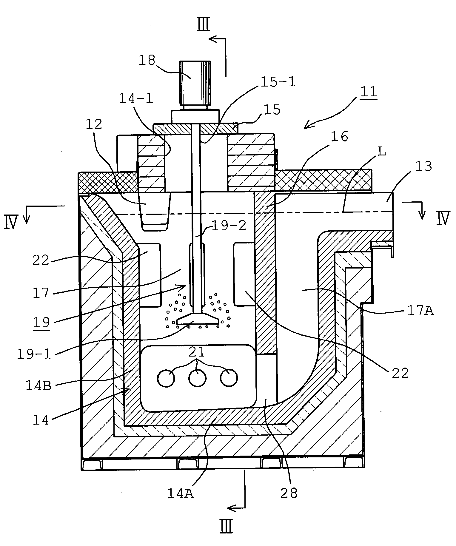
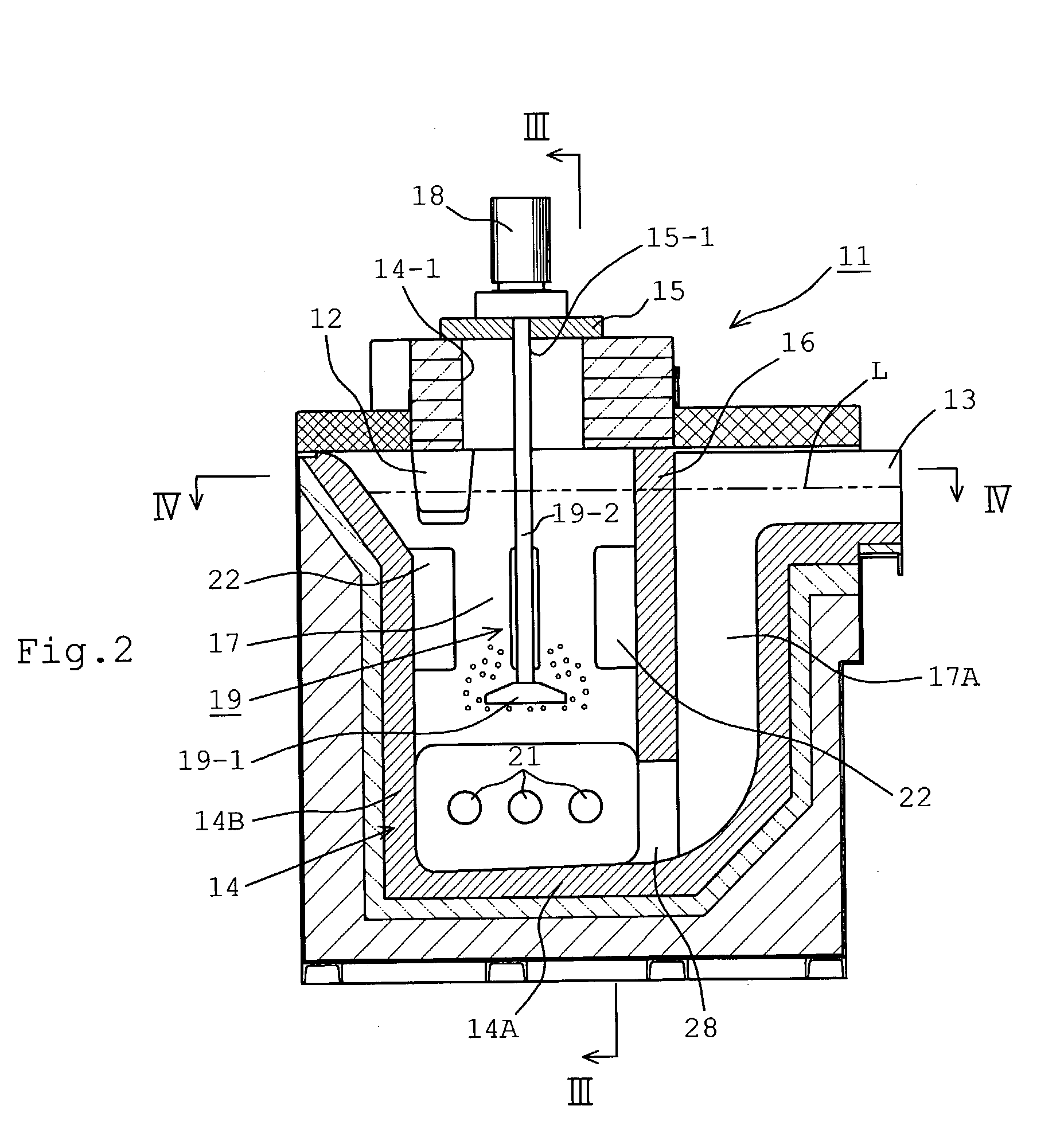
[0031] In FIGS. 2 to 4, a reference numeral 11 denotes a inline degassing apparatus 11, which includes a degassing container 14 having the inlet 12 receiving molten metal continuously flowing from the preceding process and the outlet 13 discharging molten metal to the following process after the completion of the degassing to the subsequent process. The container 14 includes an upper opening 14-1, which is covered by a lid 15. The container 14 is further provided with a partition wall 16, which is located under the lid 15. The partition wall 16 extends vertically downwardly, so that a space inside the container 14 is divided into an upstream chamber (degassing chamber) 17, to which the inlet 12 is opened and a downstream chamber 17A, to which the outlet 13 is opened. The partition wall 16 extends to a position spaced from a bottom wall 14A of the container 14, so that a relatively narrowed passageway 28 is created for connecting the chambers 17 and 17A with each other.

[0032] A refer...


PUM

PropertyMeasurementUnit
Volumeaaaaaaaaaa
Distanceaaaaaaaaaa

Abstract

An inline degassing apparatus for removing solid solution gases as well as nonmetallic inclusions from molten metal in a degassing container, to which the molten metal is continuously introduced for degassing operation and from which the degassed molten metal is continuously removed. A rotary diffusing device is arranged in the degassing container for generating bubbles of inert gas diffused into the molten metal, thereby entrapping solid solution gases as well as nonmetallic inclusions into the bubbles, which are then floated and separated. Heaters are provided, which extend, in a cantilever fashion, from a side wall of container at a position adjacent the bottom wall of the container substantially parallel to the bottom wall.

Description

[0001] 1. Field of the Invention[0002] The present invention relates to an inline degassing apparatus used for continuous degassing of nonferrous metal such as aluminum alloys and magnesium alloys.[0003] 2. Description of Related Art[0004] During refining process of nonferrous metals such as aluminum alloys and magnesium alloys, a situation is frequently occurred that nonmetallic inclusions such as oxides are generated and hydrogen gas is mixed with the molten metal. Accordingly, a high quality after processing or working can only be achieved when a separating or removal of nonmetallic inclusions from the molten metal is done prior to the processing or working. Furthermore, by an introduction of molten metal containing solid dissolved gases including mainly hydrogen gas into a mold, small cavities called "pinholes" are likely generated after the solidification, resulting in a reduction in a degree of the compactness of the finished products. Furthermore, the existence of the inclusi...

Claims


Application Information

Patent Timeline
IPC IPC(8): B22D1/00B22D11/117B22D17/30B22D41/01C22B9/05C22B21/06C22B26/22F27B14/14F27D3/14F27D3/16F27D7/06F27D11/02F27D19/00F27D27/00H05B3/78
CPCC22B9/05C22B21/066F27D3/14F27D3/16H05B3/78F27D2003/167F27D2003/168F27D2019/0003F27D2027/002F27D11/02
Inventor OHNO, YOSHIKAZUMOCHIZUKI, SHUNJI
Owner PYROTEK JAPAN
Why Eureka
Try Eureka