
Interface joint for interconnecting an electrosurgical generator and an electrosurgical instrument

an electrosurgical generator and interface joint technology, applied in the field of interface joints for interconnection of electrosurgical generators and electrosurgical instruments, can solve the problems of prolonging surgery, affecting the effect of operation, so as to reduce the chance of damage to the push rod and its resultant malfunction

Pending Publication Date: 2022-01-06
CREO MEDICAL LTD
View PDF0 Cites 1 Cited by
  • Summary
  • Abstract
  • Description
  • Claims
  • Application Information

AI Technical Summary

Benefits of technology

The present invention improves the interface joint concept discussed in another patent by reinforcing the push rod to reduce the chance of damage. Additionally, the flexible sleeve may have an internal tube that surrounds the push rod and slides with it. The invention limits the maximum slide distance of the internal tube over the push rod, reducing the chance of damage to the internal tube and its malfunction.

Problems solved by technology

When tissue is cut (divided or transected) small blood vessels called arterioles are damaged or ruptured.
For endoscopic procedures, bleeds are also undesirable, and need to be dealt with in an expedient manner, since the blood flow may obscure the operator's vision, which may prolong surgery and potentially lead to the procedure needing to be terminated and another method used instead, e.g. open surgery.
However, as a result of this increasing desiccation, particularly adjacent to the RF emitting region of the instrument (which has the highest current density of the current path through tissue), direct physical contact between the tissue and instrument can be lost.

Method used


Image

  • Interface joint for interconnecting an electrosurgical generator and an electrosurgical instrument
  • Interface joint for interconnecting an electrosurgical generator and an electrosurgical instrument
  • Interface joint for interconnecting an electrosurgical generator and an electrosurgical instrument

Examples


Embodiment Construction

; FURTHER OPTIONS AND PREFERENCES

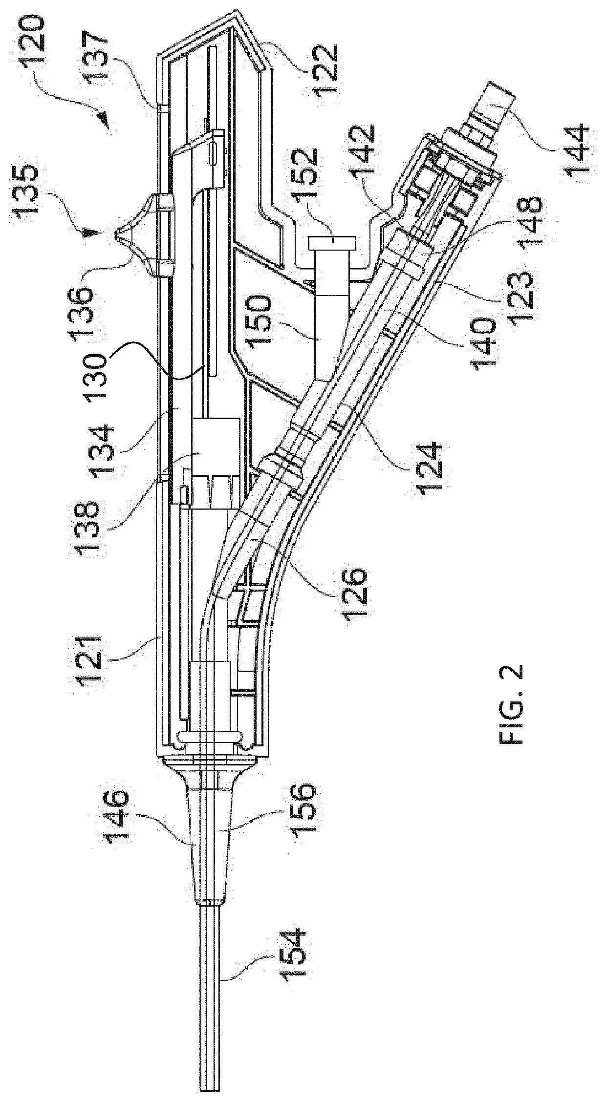
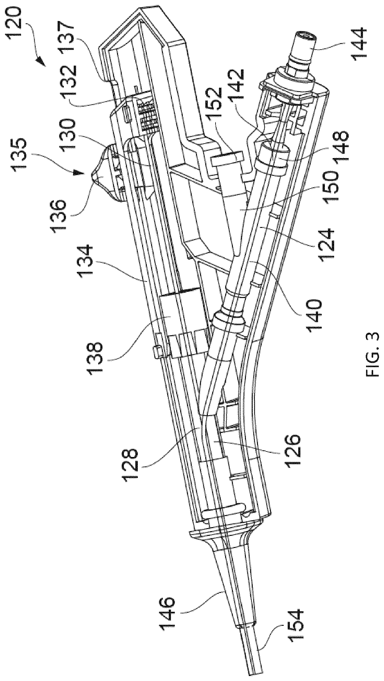
[0043]Various aspects of the present inventions are presented below in the context of an electrosurgery system that provides an electrosurgical invasive instrument for use in endoscopic procedures for the removal of polyps and malignant growths through the controlled delivery of both microwave and RF energy. However, it is to be understood that the aspects of the invention presented herein need not be limited to this particular application. They may be equally applicable in embodiments where only RF energy is required, or where only RF energy and fluid delivery is required.

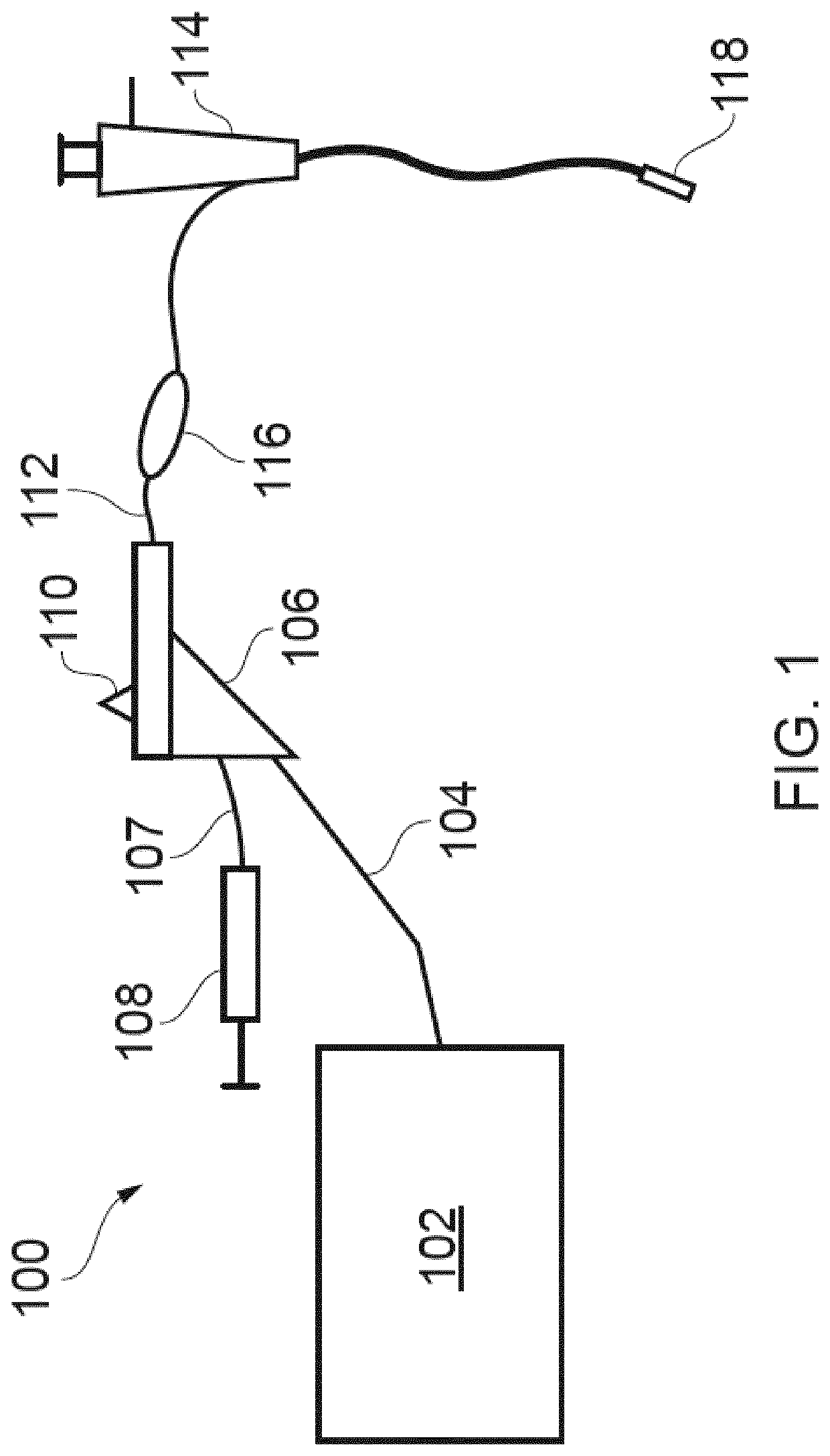
[0044]FIG. 1 is a schematic diagram of a complete electrosurgery system 100 that is capable of selectively supplying to the distal end of an invasive electrosurgical instrument any or all of RF energy, microwave energy and fluid, e.g. saline or hyaluronic acid. The system 100 comprises a generator 102 for controllable supplying electromagnetic (EM) energy. In the present embodiment...


PUM


Abstract

An interface joint for interconnecting an electrosurgical generator and an electrosurgical instrument, the interface joint comprising: a housing having: an inlet for receiving electromagnetic energy from the electrosurgical generator, and an outlet; a slidable trigger on the housing, the slidable trigger being attached to a push rod that extends out of the housing through the outlet; and a single cable assembly for connecting the outlet to the electrosurgical instrument, the single cable assembly comprising a flexible sleeve that conveys the push rod and a coaxial cable that is connected to the inlet. The interface joint may include a reinforcement element coupled to a first portion of the push rod so as to reinforce the first portion. Additionally or alternatively, the interface joint may include a slide limiting mechanism coupled to the push rod and configured to limit a maximum slide distance of an internal tube over the push rod.

Description

TECHNICAL FIELD[0001]The invention relates to an interface joint for interconnecting an electrosurgical generator and an electrosurgical instrument. The electrosurgical instrument may be for delivering electromagnetic energy (e.g. radiofrequency and / or microwave energy) into biological tissue for cutting tissue and / or for haemostasis (i.e. promoting blood coagulation).BACKGROUND TO THE INVENTION[0002]Surgical resection is a means of removing sections of organs from within the human or animal body. Such organs may be highly vascular. When tissue is cut (divided or transected) small blood vessels called arterioles are damaged or ruptured. Initial bleeding is followed by a coagulation cascade where the blood is turned into a clot in an attempt to plug the bleeding point. During an operation, it is desirable for a patient to lose as little blood as possible, so various devices have been developed in an attempt to provide blood free cutting. For endoscopic procedures, bleeds are also und...

Claims


Application Information

Patent Timeline
Patent Type & Authority Applications(United States)
IPC IPC(8): A61B18/18A61B90/00
CPCA61B18/1815A61B2018/00178A61B90/03A61B2018/00172A61B2018/1861A61B2018/00196A61B2017/00296A61B2018/0091A61B18/14A61B18/1206A61B2018/1823A61B2018/00607A61B2090/034
Inventor HANCOCK, CHRISTOPHER PAULGEOGHEGAN, LEIFMONICO, ROHANMORRIS, STEVEGULLIFORD, CRAIGHOPKINS, HUWTURNER, LOUISPLUTA, ROBERT
Owner CREO MEDICAL LTD
Learn More