Electrochromic display device and electrodeposition display device

a display device and electrodeposition technology, applied in non-linear optics, instruments, optics, etc., can solve the problems of user fatigue, user reading, and user inability to stand long-time reading

Inactive Publication Date: 2003-08-21
SONY DEUT GMBH +1
View PDF2 Cites 21 Cited by
  • Summary
  • Abstract
  • Description
  • Claims
  • Application Information

AI Technical Summary

Problems solved by technology

However, it is pointed out that emission-type displays cause much fatigue due to ergonomic reasons, and users cannot withstand long-time reading.
Additionally, there is the disadvantage that a user can read it only at the place where a computer is set.
However, also these devices cannot be used for reading over several hours or more because of the problem of power consumption in addition to the reason that the display is of an emission type.
However, reflectance of liquid crystal under no display (black-and-white display) is 30%, and visibility of such displays is much worse than prints on paper.
Therefore, users are liable to fatigue and cannot withstand long-time reading.
These methods, however, involve the problems that gaps among particles absorb light and thereby degrade the contrast, and a writing speed acceptable for practical use (within one second) cannot be attained unless raising the drive voltage to 100 V or more.
However, since light control glass and clock or watch displays do not originally need the matrix drive, they are not applicable to the use of display such as electronic paper.
Additionally, quality level of black is bad, in general, and their reflectance is still low.
Displays such as electronic paper are inevitably exposed continuously to light such as sunlight or room light because of their purposes of use.
Generally, however, organic materials exhibits poor light resistance, and are bronzed and degraded in black optical density after long use.

Method used


Image

  • Electrochromic display device and electrodeposition display device
  • Electrochromic display device and electrodeposition display device
  • Electrochromic display device and electrodeposition display device

Examples


example 2

[0099] Polymeric solid electrolyte was coated on a TFT substrate beforehand and dried and gelled similarly to Example 1. Thereafter, the substrate was introduced into the electrodeposition vessel, and electricity was supplied similarly to Example 1. As a result, polypyrole deposited on ITO electrodes in a compounded form with the matrix polymer of polymeric solid electrolyte. The substrate was removed from the electrodeposition vessel and immediately bonded to the counter electrode (second electrode), and the sample was dried under the same condition.

[0100] When the sample was driven and evaluated similarly to Example 1, the repetition number of cycles was approximately thirty million times, and the other characteristics were equivalent.

example 3

[0101] (Fabrication of Display Electrodes, and Preparation and Coating of Polymeric Solid Electrolyte)

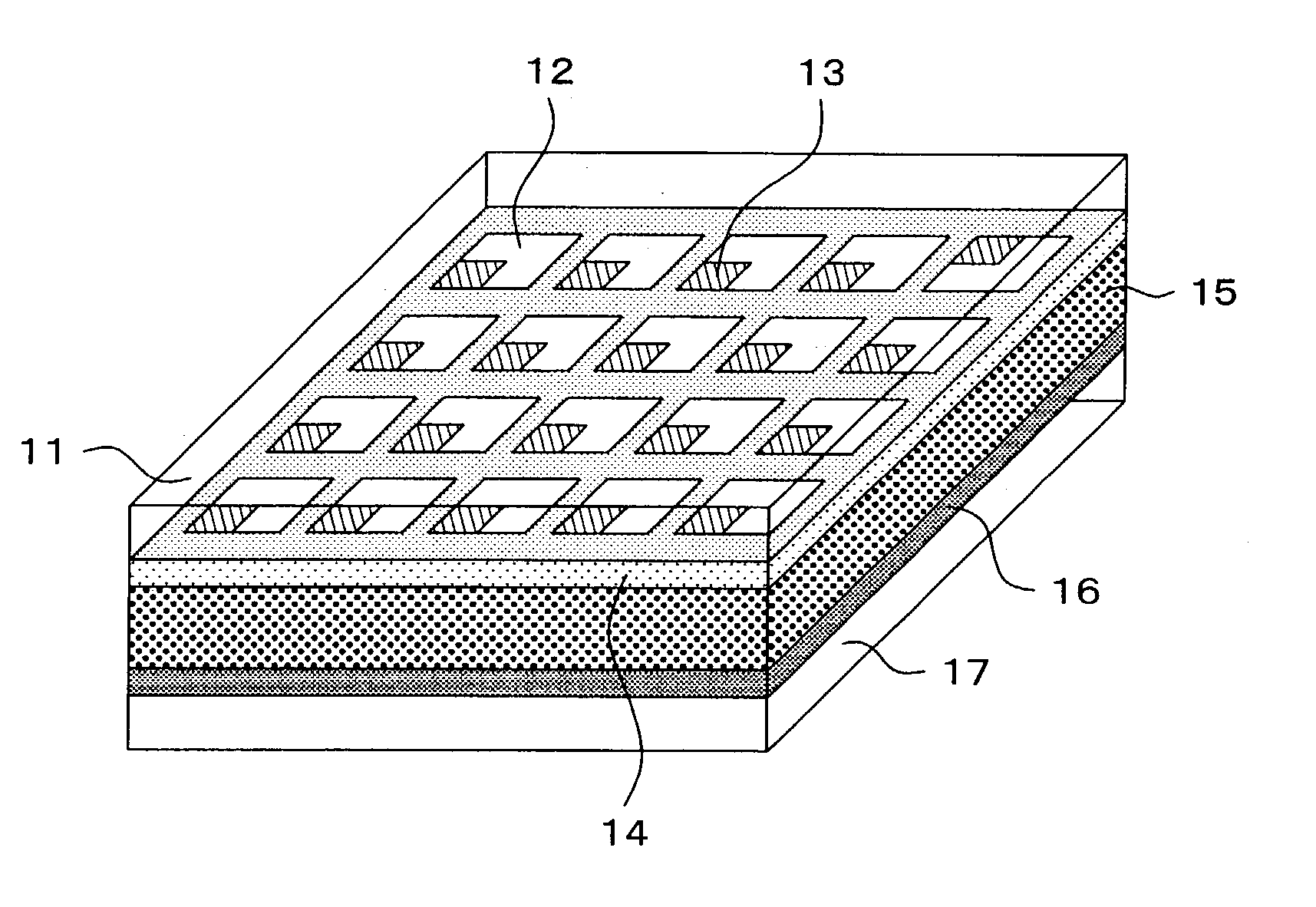
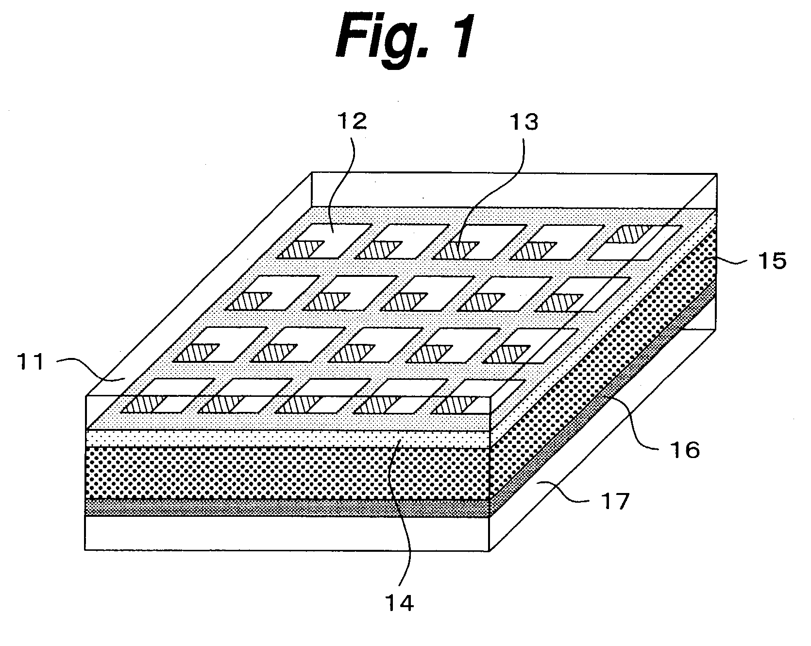
[0102] A two-dimensional arrangement of ITO films and TFT (thin film transistor) aligned by 150 .mu.m pitch were formed on a 1.5 mm thick glass substrate sized 10.times.10 cm. Thereafter, 1 weight part of polyvinylidene fluoride of molecular weight 350,000 approximately was mixed in 10 weight part of 1:1 mixture solvent of water and isopropyl alcohol containing 1.7 weight part of lithium bromide and 1.7 weight part of bismuth chloride, and the mixture was heated to 120.degree. C. to prepare a homogenous solution. Subsequently, 0.2 weight part of titanium dioxide having the mean grain size 0.5 .mu.m was added to the solution, and uniformly dispersed by homogenizer. This was next coated on the glass substrate with a doctor blade up to the thickness 60 .mu.m, then the common electrode as the second electrode, explained later, was immediately bonded, and dries by vacuum drying under 110...

example 4

[0107] A sample was prepared using the same conditions that of Example 3, excepting the use of a mixture of polyvinylidene chloride fluoride, LiBF.sub.4 and AgClO.sub.4. When the sample was driven and evaluated similarly to Example 3, the repetition number of cycles was approximately thirty million times, and the other characteristics were equivalent.


PUM

PropertyMeasurementUnit
reflectanceaaaaaaaaaa
drive voltageaaaaaaaaaa
thicknessaaaaaaaaaa

Abstract

Between each transparent pixel electrode driven by TFT as a drive device and a common electrode, a polymer layer located in contact with the transparent pixel electrode and electrically active to change in color by electrochemical oxidization or reduction and a polymeric solid electrolytic layer located in contact with the polymer layer and containing a coloring agent are interposed. since electrochemical oxidization or reduction brings about a color change, the contrast and the black concentration can be enhanced, and bronzing after long-time use does not occur.

Description

[0001] This invention relates to an electrochromic display device and an electrodeposition-type display device using a material variable in color by electrochemical oxidation and reduction as the display material, and also relates to a display apparatus using them.[0002] Along with recent dissemination of networks, documents having heretofore distributed in form of printed matters have come to be distributed in form of so-called electronic documents. Additionally, more and more books and magazines are also becoming delivered in form of so-called electronic publications.[0003] Conventional way of accessing to these kinds of information is to read from CRT or liquid crystal displays of computers. However, it is pointed out that emission-type displays cause much fatigue due to ergonomic reasons, and users cannot withstand long-time reading. Additionally, there is the disadvantage that a user can read it only at the place where a computer is set.[0004] Together with recent distribution ...

Claims


Application Information

Patent Timeline
Patent Type & Authority Applications(United States)
IPC IPC(8): G02F1/15G02F1/17
CPCG02F1/15G02F1/1508G02F2001/1635G02F2001/1519G02F2001/1515G02F1/15165G02F2001/164
Inventor SHINOZAKI, KENJIYASUDA, AKIONODA, KAZUHIROUDAKA, TORUKUWAHARA, MIEKO
Owner SONY DEUT GMBH
Why Eureka
Try Eureka