
Fuel cell system

Inactive Publication Date: 2003-09-04
DENSO CORP
View PDF6 Cites 26 Cited by
  • Summary
  • Abstract
  • Description
  • Claims
  • Application Information

AI Technical Summary

Benefits of technology

[0008] It is an another object of the present invention to reduce the size of the fuel cell system while the fuel cell can be rapidly warmed-up using the small heating source.
[0009] It is a further another object of the present invention to effectively heat a part area of the fuel cell with a simple structure.
[0010] According to the present invention, in a fuel cell system having a fuel cell for generating electric power using a fuel gas, the fuel cell has a plurality of stacked cells, and a part of each cell is collectively heated when the fuel cell is warmed up in a warm-up operation. Since a part of each cell of the fuel cell can generate electric power by collectively heating the part thereof, the other part of each cell of the fuel cell can be heated using self heat generation due to the power generation in the part of the fuel cell. Therefore, a temperature distribution between the cells can be made uniform, and heating quantity required for warming up the fuel cell can be made smaller in the warm-up operation, thereby rapidly heating the fuel cell using a small heating source even in a low temperature environment. Specifically, in the present invention, the fuel cell has therein a plurality of thermal medium passages that are provided independently such that a thermal medium independently flows through the thermal medium passages. Therefore, a part area of the fuel cell can be effectively rapidly heated by using a heating device having a small heat capacity to generate electrical power, and the other part thereof can be heated using the thermal medium and the generated electrical power in the one part as the heating sources. Accordingly, a part area of the fuel cell can be effectively heated with a simple structure of the independent thermal medium passages in the warm-up operation of the fuel cell.
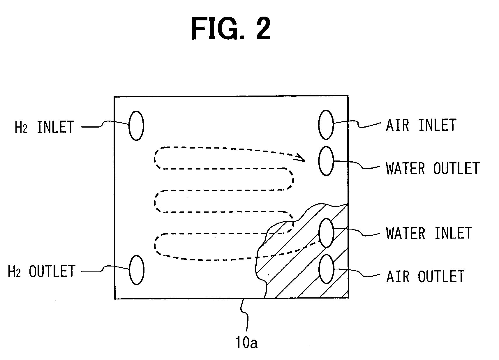
[0011] Preferably, the thermal medium passages are provided in parallel to each other on surfaces of the cells in a direction approximately perpendicular to the stack direction of the cells to form plural lines, and the thermal medium passages of adjacent cells in the stack direction are provided to communicate with each other on each line. Accordingly, the thermal medium passage can be readily formed with a simple structure. Here, the thermal medium passages can be arranged adjacent to each other in the stack direction, on each line. In this case, the passage length of the thermal medium passage in the stack direction can be made shorter while a sufficient amount of the thermal medium can be circulated in the fuel cell.
[0012] Preferably, each of thermal medium passages has an inlet and an outlet at its two ends, respectively, the inlets of the thermal medium passages are connected to each other in the stack direction on each line, and the outlets of the thermal medium passages are connected to each other in the stack direction on each line. In this case, the inlets of the thermal medium passages are provided in common to communicate with a one inlet passage through which the thermal medium is introduced into the inlets of the thermal medium passages, and the outlets of the thermal medium passages are provided independently to be separated from each other at different lines. Alternatively, the outlets of the thermal medium passages are provided in common to communicate with a one outlet passage through which the thermal medium from the outlets of the thermal medium passages is discharged, and the inlets of the thermal medium passages are provided independently to be separated from each other at different lines. Accordingly, heat due to the electrical power in the partial area of the fuel cell can be readily transmitted through the common inlet or the common outlet, and the warm-up effect in the fuel cell can be further improved.
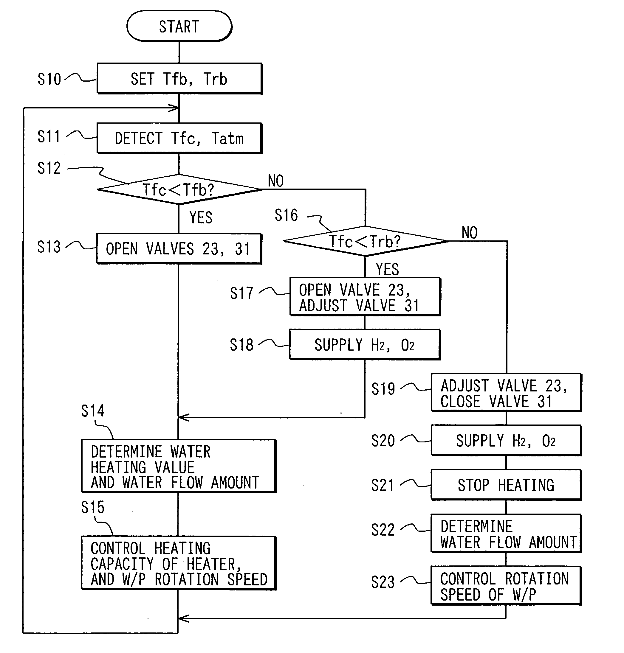
[0013] In the fuel cell system of the present invention, a temperature detection device is provided for detecting a temperature of the thermal medium flowing from an outlet of the fuel cell, and a controller controls the thermal medium circulation device based on the temperature of the thermal medium detected by the temperature detection device. When the controller determines that the temperature of the thermal medium detected by the temperature detection device is lower than a predetermined temperature, the controller outputs an operation signal to the thermal medium circulation device so as to circulate the thermal medium heated by the heating device into a part of the thermal medium passages. On the other hand, when the controller determines that the temperature of the thermal medium detected by the temperature detection device is increased higher than the predetermined temperature, the controller outputs an operation signal to the thermal medium circulation device so as to circulate the thermal medium heated by the heating device into the fuel cell from the part of the thermal medium passages to all the thermal medium passages in accordance with a temperature increase of the thermal medium. Accordingly, the warm-up operation of the fuel cell can be effectively controlled.

Problems solved by technology

However, in this method, during the warm-up operation of the fuel cell, some stack parts generate electric power, and the other stack parts generate no electric power.
Further, fuel gas such as oxygen and hydrogen is needed to be supplied to each stack part generating electric power, and it is unnecessary to supply the fuel gas to each stack part where no electric power is generated.

Method used


Image

  • Fuel cell system
  • Fuel cell system
  • Fuel cell system

Examples


seventh embodiment

[0131] (Seventh Embodiment)

[0132] In a fuel cell system of the seventh embodiment, a heating device using electric power generated by the fuel cell 10 is added to the fuel cell system described in the above sixth embodiment. In the seventh embodiment, the same portions as the sixth embodiment are indicated by the same reference numerals, and description thereof is omitted.

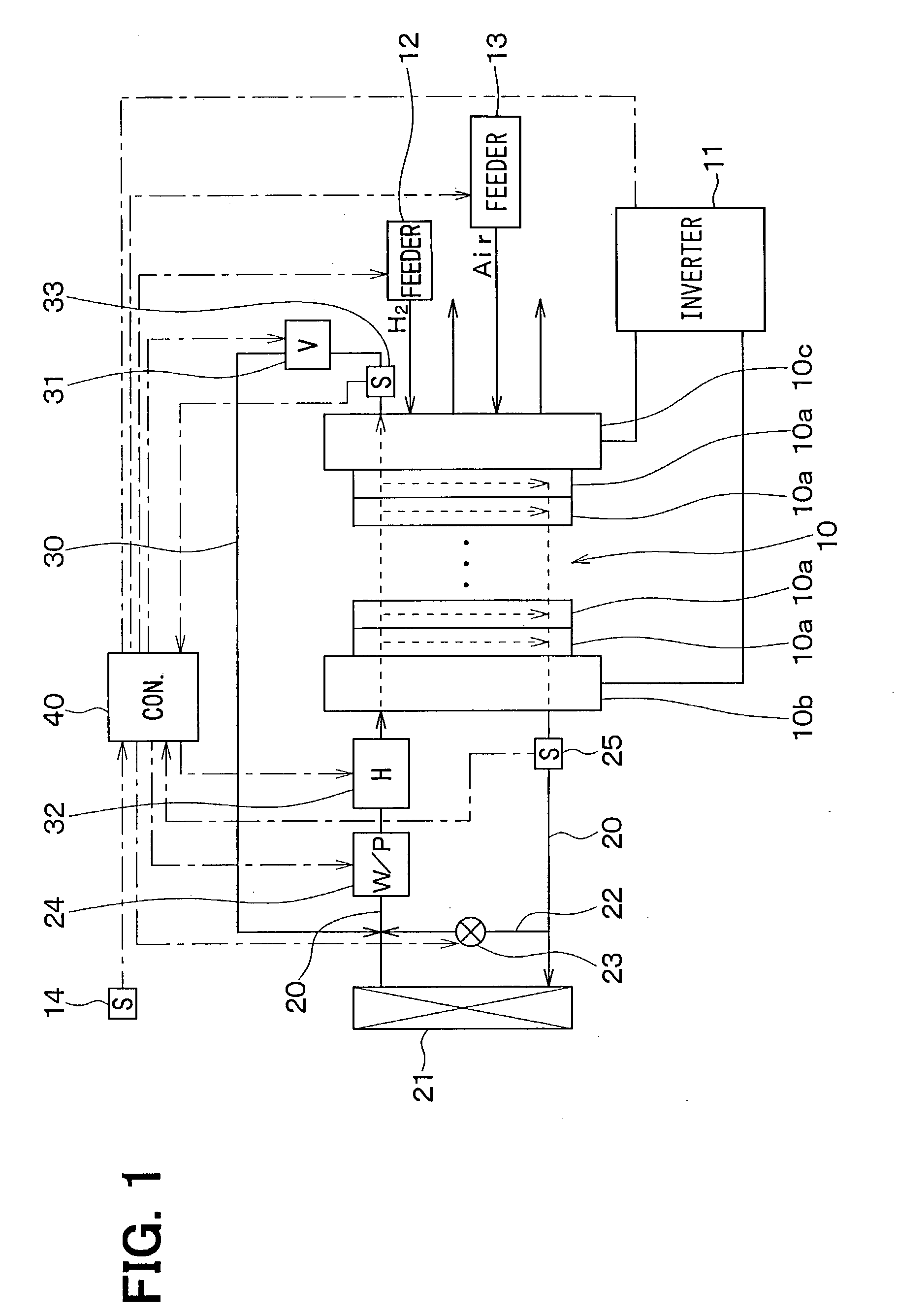
[0133] FIG. 12 shows an entire structure of the fuel cell system of the seventh embodiment. As shown in FIG. 12, an electric heater 39 is provided in the heating path 26. The electric heater 39 heats cooling water flowing in the heating path 26 using electric power supplied from the fuel cell 10.

[0134] Electric power generated by the fuel cell 10 is consumed as motive power of a main motor for running a vehicle, as motive power of peripheral accessories for charging a secondary cell and the like through the inverter 11. However, a vehicle is generally stopped during the warm-up operation of the fuel cell 10, and ch...

eighth embodiment

[0136] (Eighth Embodiment)

[0137] In a fuel cell system of the eighth embodiment, as shown in FIG. 14, the first temperature sensor 33 is eliminated from the fuel cell system described in the above seventh embodiment. In the eighth embodiment, the same portions as the seventh embodiment are indicated by the same reference numerals, and description thereof is omitted.

[0138] As shown in FIG. 14, the first temperature sensor 33, provided in the bypath path 30 around the water outlet of the fuel cell 10 in FIG. 12, is eliminated. Further, the second temperature sensor 25, provided in the thermal medium circulation path 20 around the water outlet of the fuel cell 10 in FIG. 12, is provided in the thermal medium circulation path 20 at a downstream side of a connection point between the thermal medium circulation path 20 and the bypass path 30.

[0139] According to the eighth embodiment, when a part of the fuel cell 10 is collectively heated by circulating cooling water only in the bypass pat...

ninth embodiment

[0141] (Ninth Embodiment)

[0142] In the ninth embodiment, an arrangement position of the heater 32 is different from that in the above-described sixth embodiment. In the ninth embodiment, the same portions as the sixth embodiment are indicated by the same reference numerals, and detail description thereof is omitted.

[0143] As shown in FIG. 16, in the ninth embodiment, the bypass path 30 is connected to the thermal medium circulation path 20 at a position downstream from the water pump 24 and upstream from the fuel cell 10. The heater 32 is provided in the bypass path 30 at a downstream side of the bypass water pump 38. In this construction, when a part of the fuel cell 10 is collectively heated, cooling water is circulated into the bypass water pump 38, the heater 32 and the part of the fuel cell 10, in this order. Further, the radiator bypass path 22 through which cooling water bypasses the radiator 21, and the temperature control valve 23 for adjusting the amount of cooling water f...


PUM

PropertyMeasurementUnit
temperatureaaaaaaaaaa

Abstract

In a fuel cell system, a fuel cell includes plural stacked cells, a circulation passage for circulating a thermal medium to the fuel cell. The fuel cell has therein a plurality of thermal medium passages through which the thermal medium flows, and the thermal medium passages are provided such that the thermal medium from the circulation passage independently flows through the thermal medium passages. The thermal medium passages in the fuel cell have inlet portions from which the thermal medium is introduced, and outlet portions from which the thermal medium is discharged. In the fuel cell system, at least one-side portions among the inlet portions and the outlet portions are provided independently. Accordingly, a circulation area of the thermal medium in the fuel cell can be selectively changed, and a part of the fuel cell can be effectively heated to generate electrical power in this part.

Description

[0001] This application is a CIP application of U.S. application Ser. No. 10 / 207,355, filed on Jul. 29, 2002. The present application is related to Japanese Patent Applications No. 2001-244213 filed on Aug. 10, 2001, No. 2001-383667 filed on Dec. 17, 2001, No. 2002-21635 filed on Jan. 30, 2002, No. 2002-184948 filed on Jun. 25, 2002, No. 2002-283009 filed on Sep. 27, 2002, and No. 2002-341079 filed on Nov. 25, 2002, the contents of which are hereby incorporated by reference.[0002] 1. Field of the Invention[0003] The present invention relates to a fuel cell system having a fuel cell that generates electric power by an electrochemical reaction between oxygen and hydrogen. The fuel cell system is suitably used for a movement body such as a vehicle, a ship and a portable generator.[0004] 2. Description of Related Art[0005] In a fuel cell for generating electric power using a chemical reaction between hydrogen and air (oxygen), moisture (water) is generated in the fuel cell due to power ...

Claims


Application Information

Patent Timeline
Patent Type & Authority Applications(United States)
IPC IPC(8): H01M8/02H01M8/04H01M8/24
CPCH01M8/04029H01M8/04067H01M8/04074H01M8/04097H01M8/04126Y02T90/32H01M8/04358H01M8/04768H01M8/241H01M2250/20Y02E60/50H01M8/04223H01M8/0263H01M8/0267H01M8/04302H01M8/2483Y02T90/40H01M8/0258H01M8/04225
Inventor KUDOU, HIROYASUSAITO, TOMOHIROKAWAI, TOSHIYUKIOKAMOTO, KUNIOOSAKI, AKIMASA
Owner DENSO CORP
Learn More