
Automatic software production system

a software production system and software technology, applied in the direction of source code creation/generation, specific program execution arrangements, program control, etc., can solve the problems of difficult to clarify the method semantics, difficult to estimate the completion time, and the opportunity for programming errors

Inactive Publication Date: 2003-09-04
IBORRA JOSE +1
View PDF0 Cites 201 Cited by
  • Summary
  • Abstract
  • Description
  • Claims
  • Application Information

AI Technical Summary

Benefits of technology

[0025] In the preferred species described herein, the process of creating the Conceptual Model is done using a graphical user interface to represent the various objects, etc. that comprise the model visually. In other embodiments, the Conceptual Model may be drafted directly in a formal language using a plain old text-based interface or any word processing application. This is done by a SOSY modeler after determining the nature of the problem to be solved and all the other information needed to model the code to be written in a formal language. As long as the Conceptual Model is written in a formal language, it can be validated, and that validation process is a key factor in generating complete and error free code. This substantially reduces the time to market for the application's final code.
[0026] The applicants feel that the front end processing to generated a high level repository in a formal language that records the details of the Conceptual Model is an invention standing alone. This is because this high level repository can be coded manually and there will be far fewer errors caused by incomplete information, ambiguous terms, etc.
[0032] The second point of novelty subgenus relates to how the Conceptual Model is actually built by the SOSY modeler. In the preferred species within this first subgenus, the Conceptual Model is built by using a graphical user interface to define objects and relationships between objects, state transitions and most if not all the other items that go into the Conceptual Model that is encoded into the formal language. This just makes it easier for the SOSY modeler to use the formal language by alleviating the need for the SOSY modeler to know all the details of the syntax and semantics of the formal language. In other species within the first subgenus however, the SOSY modeler can use a text based interface or any other type of interface to record the statements which together comprise the Conceptual Model.
[0043] By generating the application code from the validated formal specification, error-free source code strategies can be employed, freeing the developer from having to manually produce the source code or extend an incomplete prototype. Therefore, the error-prone, manual programming phase of the traditional software engineering process is eliminated, and the testing and debugging time is greatly reduced. In one example, the software development time of an application was reduced to 2.02% (or 8.5% worst case) of the original time. In other words, performance has been benchmarked by a reputable software tool evaluation company to be 12 to 47 times faster than similar projects using other competing software products. Software maintenance is also reduced, because the traditional coding, testing, and revalidation cycles are eliminated.
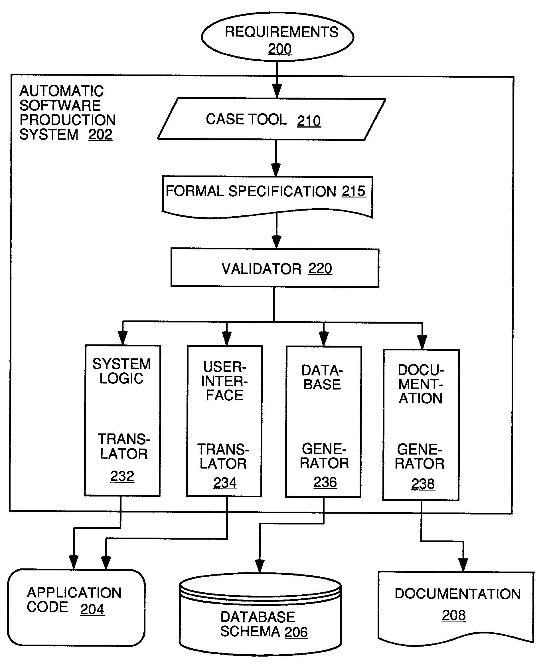
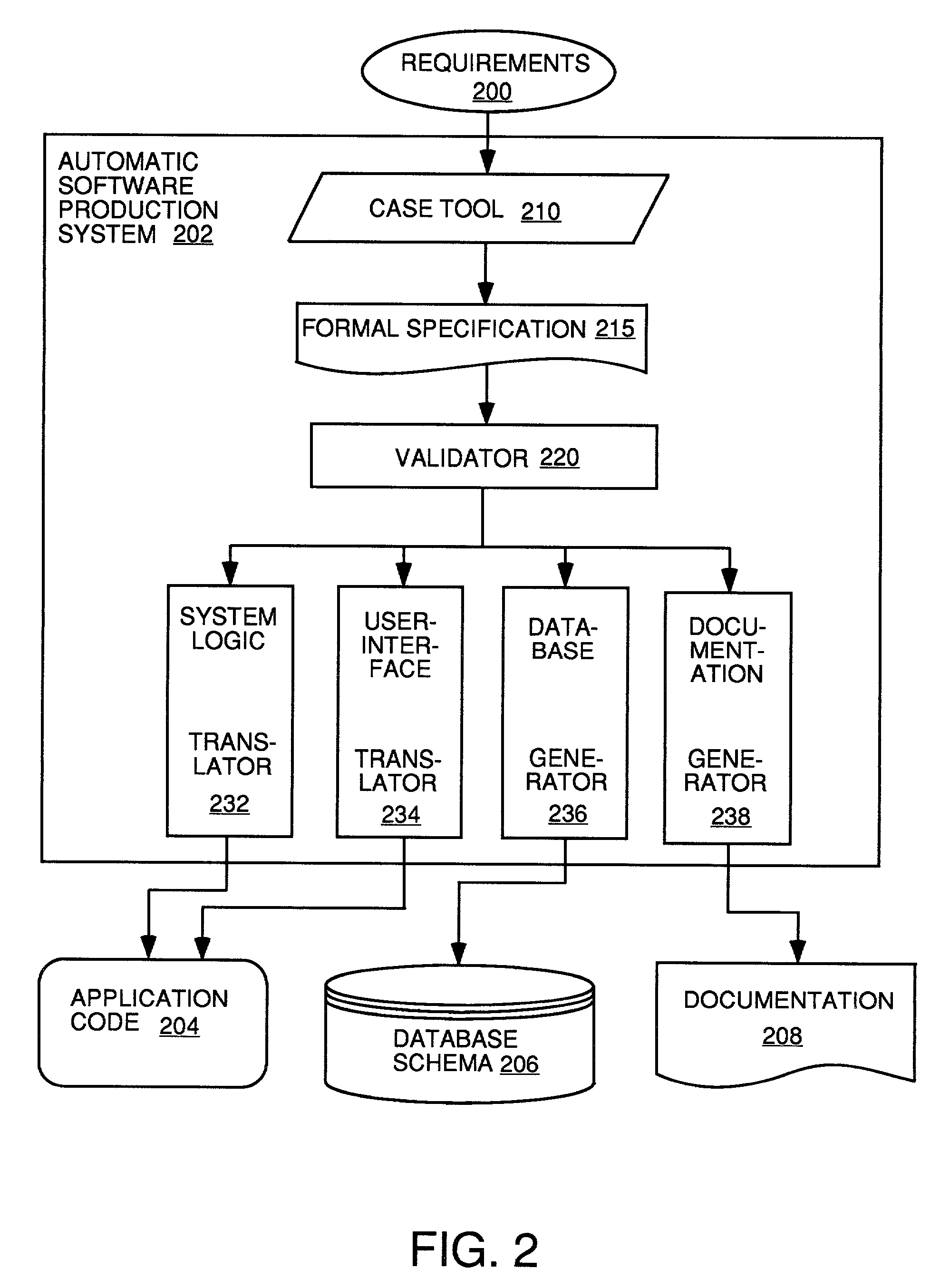
[0044] One aspect of the present invention springs from the insight that ambiguity is a major source of programming errors associated with conventional object-oriented and higher-order programming languages such as C++. Accordingly, an automated software production tool, software, and methodology are provided, in which a graphical user interface is presented to allow a user to input unambiguous formal requirements for the software application. Based on the formal requirements input for the software application, a formal specification for the software application is produced and validated, from which the software application is generated. By generating the software application directly from an unambiguous, validated formal specification, the software developer can avoid the programming errors associated with conventional programming languages, and instead work directly in the problem space. In one embodiment, error handling instructions are also produced when the software application is generated so as to create a robust, final software application.

Problems solved by technology

Having to refine the system requirements is one of the most serious problems that might occur, because any modification to the requirements necessitates a redevelopment of the source code, starting the process all over again.
Thus, the testing and debugging phase is the longest phase in the software engineering process and the most difficult to estimate completion times.
Nevertheless, some mismatch between the problem space and the solution space remains, which gives rise to an opportunity for programming errors.
Because of the programming errors, it is necessary to undergo an extensive testing and debugging phase to isolate and fix the software faults.
Combining structured and objected-oriented techniques in a single method, however, makes it difficult to clarify the method semantics; thus, effective tool support is necessary for checking consistency.
Although these approaches are of some help for the first phase, i.e. in refining the requirements before the computer application is coded, they do not address the main source for the lack of productivity during later phases of the software engineering process, namely the programming and testing / debugging phases.
The newly developed code, due to the mismatch between the problem space and the solution space, will commonly contain coding errors and will need to be extensively tested and debugged.
The rule-rewriting approach of OBLOG, moreover, fails to address this need, because the difficulties associated with programming are merely shifted one level back, to the development of the rewriting rules in an unfamiliar, proprietary language.
For example, if a statement in the model attempted to add a floating point number to an alphanumeric string, that would be semantically incorrect, and would be detected in the validation process.
The validation process does not confirm that the model created correctly models the problem.
Thus, such conventional prototypes have primitive user interfaces that are unacceptable for final, customer-ready software application.
These three models, however, are insufficient by themselves to specific a complete application, because a complete application also requires a user interface.

Method used


Image

  • Automatic software production system
  • Automatic software production system
  • Automatic software production system

Examples


Embodiment Construction

to Create a Conceptual Model for a Software Program to Manage Expense Reporting by Employees, Expense Report Approvals and Payments

[0224] Requirements: The Problem to be Managed by the Computer Program to be Automatically Generated

[0225] The system will manage the expense reporting of employees, expense approvals and payments.

[0226] Expenses will reflect both: pattern currency and its equivalent to other currency. Expense line for user input of an expense will only allow input in the pattern currency.

[0227] Employees may present an expense report when they have supported expenses on behalf of the company. Typically, the expenses are associated to a certain project or specific task.

[0228] At presenting the expense report, supporting tickets and receipts will be attached and prior expense advances will be reflected. Advances must be discounted out from the expense report balance.

[0229] The expense report, once presented, must be authorized by a manager responsible for payment of expen...


PUM


Abstract

An automated software production system is provided, in which system requirements are captured, converted into a formal specification, and validated for correctness and completeness. In addition, a translator is provided to automatically generate a complete, robust software application based on the validated formal specification, including user-interface code and error handling code.

Description

[0001] This is a continuation-in-part application of a prior U.S. patent application filed Apr. 4, 2000, Ser. No. 09 / 543,085. The present invention relates to computer systems and more particularly to an automatic software production system and methodology.[0002] This application claims subject matter that is related to the subject matter claimed in two other continuation-in-part applications entitled "Automatic Software Production System", filed on ______ and ______, and having Ser. Nos. ______ andCOMPUTER PROGRAM LISTING APPENDIX[0003] 1. Field of the Invention[0004] The assembly code computer program listing having file name TOTAL.ASM size 39,107,073 bytes, created on May 23, 2001 which was submitted in duplicate with this patent application on a single CD-ROM is hereby incorporated by reference. The file is in TXT format on a disc compatible with IBM-PCs and the Windows 98 operating system, and can be opened by any word processor.[0005] 2. Background of the Invention[0006] Softw...

Claims


Application Information

Patent Timeline
IPC IPC(8): G06F9/44
CPCG06F8/30G06F8/73G06F17/30371G06F8/35G06F16/2365
Inventor IBORRA, JOSEPASTOR, OSCAR
Owner IBORRA JOSE
Learn More