High performance, low volume, non-contact liquid dispensing apparatus and method

a liquid dispensing apparatus and non-contact technology, applied in the field of high performance, low volume, non-contact liquid dispensing apparatus and method, can solve the problems of rate-limiting hardware, reducing volume, and lowering costs by an order of magnitud

Active Publication Date: 2003-09-11
BIONEX SOLUTIONS
View PDF58 Cites 47 Cited by
  • Summary
  • Abstract
  • Description
  • Claims
  • Application Information

AI Technical Summary

Benefits of technology

[0014] The present invention provides an apparatus and method for delivering repetitive, precision, low volume liquid dispensing from a dispensing orifice of a non-contact liquid dispensing apparatus. An elongated communication passageway of the dispensing apparatus is defined by interior walls having one end in fluid communication with a system fluid reservoir and an opposite end terminating at the dispensing orifice. A system fluid is placed in the communication passageway extending substantially continuously from the system fluid reservoir to the dispensing orifice. A relatively small volume of gaseous fluid is aspirated through the dispensing orifice, and into the communication passageway in a manner such that the gaseous fluid extends substantially continuously across the transverse cross-sectional dimension of the communication passageway. Subsequently, a dispensing liquid is aspirated through the dispensing orifice and into the communication passageway in a manner such that the relatively small volume of aspirated gaseous fluid forms a minute, unitary air gap fully enclosed between the interior walls of the communication passageway and a liquid interface between the system fluid and the dispensing liquid contained in the communication passageway. This air gap substantially prevents dispersion and dilution therebetween at the liquid interface. To effect dispensing, a rapid pressure pulse with a predetermined pulse width is applied to the system fluid upstream from the minute air gap, causing the pressure pulse to traverse the minute air gap to the dispensing liquid without substantial fluid compression of the minute air gap. This enables substantially accurate, relatively small volume, non-contact liquid dispensing of the dispensing liquid from the dispensing orifice.
[0015] Accordingly, it has been found that aspirating smaller volumes of in-line gas significantly improve the volumetric dispensing precision and reproducibility not capable with volumes greater than about 5.0 microliters. Applying a single, continuous air gap in the range of about 250 nanoliters to about 2.0 microliters, extending across the transverse cross sectional dimension of the communication passageway, precision low volume, non-contact, liquid dispensing can be delivered from these non-contact, liquid dispensing devices while maintaining sufficient separation of the liquids at the interface to minimize dispersion and dilution by the system fluid.
[0016] These discrete air gaps essentially behave as substantially incompressible fluids, unlike air gaps larger than about 10 microliters for the given diameters. As the pressure pulse propagates down the communication passageway (originating from the back pressure and the opening and closing of the dispensing actuator as will be described below), the pressure pulse can traverse this discrete air gap interface without significant loss of energy due to compliance. This enables greater control of the pressure pulse across the dispensing orifice for repetitive, precise, low volume, non-contact liquid dispensing in the picoliter to microliter. In one specific embodiment, the system fluid is pressurized with a gas at a substantially constant back pressure. Thus, a rapid actuation dispensing valve in fluid communication with the communication passageway, positioned downstream from the system fluid reservoir and upstream from the air gap, can be actuated to perform fluid flow. The back pressure, in one arrangement, is in the range of about 2.0 psi to about 15.0 psi, and preferably about 8.0 psi. The pressurizing gas may be selected as one that suppresses in-gassing, and is substantially insoluble to the system fluid. One such gas is helium.
[0018] In another aspect of the present invention, trapped gases in a system fluid contained in an actuation valve may be purged and expelled through the dispensing orifice of these non-contact liquid handling systems. The system fluid is initially flowed through the actuation valve and into the communication passageway between the one end of the pressure tube and the dispensing orifice such that the actuation valve and the communication passageway are converted from a dry state to a hydraulic state. By rapidly actuating the actuation valve between a closed condition, preventing flow of the system fluid through the actuation valve from the system fluid reservoir to the dispensing orifice, and an opened condition, enabling fluid flow of the system fluid through the communication passageway, trapped gases in the actuation valve and corresponding communication passageway may be purged and expelled through the dispensing orifice.

Problems solved by technology

Reduced volumes can lower costs by an order of magnitude but conventional liquid-handling devices fail at the required volumes.
The rate-limiting hardware is low volume liquid transfer technology that is robust and scalable for compounds of interest.
This approach, however, is inherently volumetrically inaccurate since the amount of fluid adhered to the pin tool surface can vary with each cycle.
Moreover, due to "wicking" of the drops, relatively small dispensing volumes, on the order of picoliters, cannot be repetitively attained with the sufficient accuracy required for scaled-down, high throughput screening assays when delivering on dry surfaces.
Another problem associated with this capillary contact dispensing technique is that it is more vulnerable to inadvertent cross-contamination of the tool tip and target sites, especially when manipulating multiple reagents and the target site density is high.
Further, fragile biochemical coatings are often employed on the surface of the test sites that can be easily damaged by the tips of the pin tools during depository contact therebetween.
While this approach is capable of accurate reagent delivery of low volumes on the order of picoliters, one problem associated with these systems is that dedicated or fixed sample reservoirs are required which are directly fluidly coupled to the dispense orifices of the piezoelectric head.
The application of this non-contact technique, however, is labor intensive when sub-microliter volumes of multiple reagents are required.
Moreover, volumetric precision, at picoliter levels are in part due to small dispensing orifice diameters that are subject to frequent plugging.
The scalability of these systems is also reduced since the small diameter of the orifice significantly limits the volume dispense per pulse.
One problem associated with these designs, however, is that the solenoid base actuator must be positioned in-line with the dispense flow path.
Accordingly, the flow of drawn reagent sample through the components of the dispensing actuator can cause detrimental stiction.
Ultimately, volumetric delivery imprecision results, as well a prematurely reducing the life of the dispensing actuator.
However, the aspiration of large overfill volumes is required due to dispersion or dilution effect at the liquid interface between the sample.backslash.reagent and the system fluid.

Method used


Image

  • High performance, low volume, non-contact liquid dispensing apparatus and method
  • High performance, low volume, non-contact liquid dispensing apparatus and method
  • High performance, low volume, non-contact liquid dispensing apparatus and method

Examples


Embodiment Construction

[0043] While the present invention will be described with reference to a few specific embodiments, the description is illustrative of the invention and is not to be construed as limiting the invention. Various modifications to the present invention can be made to the preferred embodiments by those skilled in the art without departing from the true spirit and scope of the invention as defined by the appended claims. It will be noted here that for a better understanding, like components are designated by like reference numerals throughout the various figures.

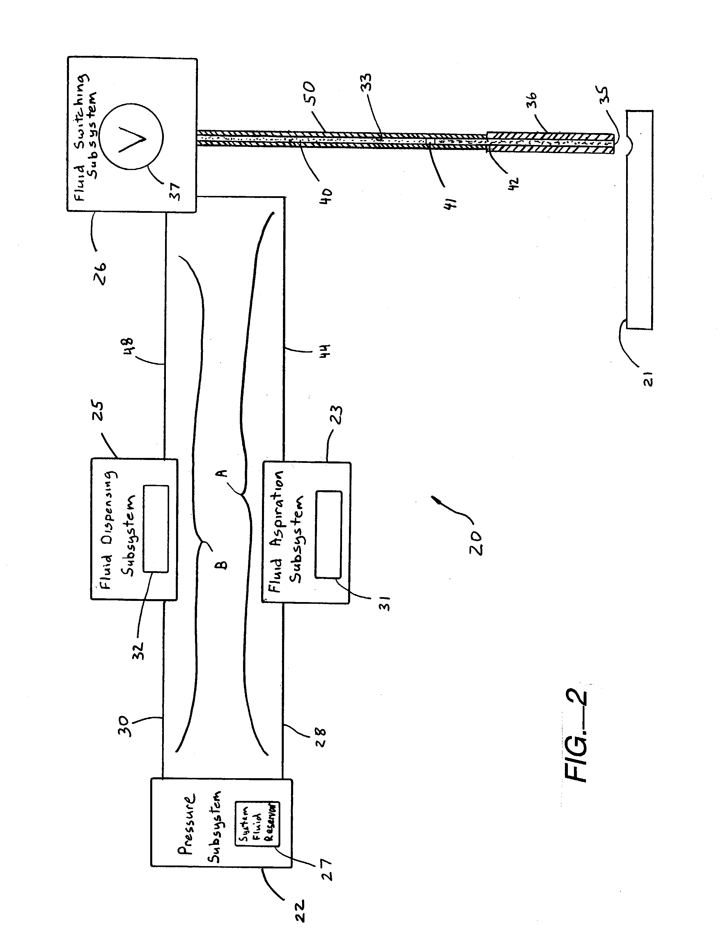
[0044] Referring now to FIG. 2, a non-contact liquid handling method and system, generally designated 20, is provided which is capable of precise low volume, liquid dispensing onto a target or destination substrate surface 21. Broadly, in one specific embodiment, the liquid handling system 20 includes a pressure subsystem 22, a fluid aspiration (input) subsystem 23, a fluid dispensing (output) subsystem 25 and a fluid switching su...


PUM

PropertyMeasurementUnit
pressureaaaaaaaaaa
pressureaaaaaaaaaa
volumeaaaaaaaaaa

Abstract

An apparatus and method for delivering repetitive, precision, low volume liquid dispensing from a dispensing orifice of a non-contact liquid dispensing apparatus. An elongated communication passageway of the dispensing apparatus is defined by interior walls having one end in fluid communication with a system fluid reservoir and an opposite end terminating at the dispensing orifice. A system fluid is placed in the communication passageway extending substantially continuously from the system fluid reservoir to the dispensing orifice. A relatively small volume of gaseous fluid is aspirated through the dispensing orifice, and into the communication passageway in a manner such that the gaseous fluid extends substantially continuously across the transverse cross-sectional dimension of the communication passageway. Subsequently, a dispensing liquid is aspirated through the dispensing orifice and into the communication passageway in a manner such that the relatively small volume of aspirated gaseous fluid forms a minute, unitary air gap fully enclosed between the interior walls of the communication passageway and a liquid interface between the system fluid and the dispensing liquid contained in the communication passageway. This minute air gap substantially prevents dispersion and dilution therebetween at the liquid interface. To effect dispensing, a rapid pressure pulse with a predetermined pulse width is applied to the system fluid upstream from the minute air gap, causing the pressure pulse to traverse the minute air gap to the dispensing liquid without substantial fluid compression of the minute air gap. This enables substantially accurate, relatively small volume, non-contact liquid dispensing of the dispensing liquid from the dispensing orifice.

Description

RELATED APPLICATION DATA[0001] The present application claims priority under 35 U.S.C. .sctn.119 to U.S. Provisional Application Serial No. 60 / 351,858 (Attorney Docket No. INVDP004P), naming Johnson et al. inventors, and filed Jan. 25, 2002, and entitled METHODS FOR HIGH-PERFORMANCE, LOW-VOLUME DISPENSING, the entirety of which is incorporated herein by reference in its entirety for all purposes.[0002] The present invention relates to methods and apparatus for liquid handling, and more particularly, relates to methods and apparatus for non-contact, high performance, relatively low volume liquid dispensing.[0003] Advances in Life Sciences, particularly in genomics and proteomics, have greatly increased the potential number of reactions and analyses that must be performed by the biotechnology and pharmaceutical industries. An estimated 30 million tests are required to screen a typical pharmaceutical company's compound library against target receptors. The typical number of tests will ...

Claims


Application Information

Patent Timeline
Patent Type & Authority Applications(United States)
IPC IPC(8): B01L3/02G01N37/00G01N35/00G01N35/10
CPCB01L3/021Y10T436/15B01L2200/143B01L2200/148B01L2300/14B01L2400/02B01L2400/0487B01L2400/06B01L2400/0633B01L2400/0666G01N35/00594G01N35/00712G01N35/1002G01N35/1016G01N35/1065G01N2035/00237G01N2035/1041G01N2035/1044Y10T436/2575B01L3/0268Y10T137/3003
Inventor JOHNSON, JAMES E.PICHA, NEIL R.STORMS, CRAIG M.MARTIN, DAVID A.
Owner BIONEX SOLUTIONS
Why Eureka
Try Eureka