Thermally applied coating for piston rings, consisting of mechanically alloyed powders

Inactive Publication Date: 2003-09-25
FEDERAL MOGUL BURSCHEID
View PDF4 Cites 127 Cited by
  • Summary
  • Abstract
  • Description
  • Claims
  • Application Information

AI Technical Summary

Benefits of technology

0003] By their constant contact at the cylinder barrel, piston rings are subject to constant sliding wear. This is expressed both in the abrasive degradation of the piston ring surface or its coating and in the partial transfer of material from the cylinder surface to the piston ring surface and vice versa. It is possible by using adapted coatings to minimize these negative affects. Consequently, particle-reinforced hard chromium layers exhibit better resistance to abrasion than uncoated or nitrated rings (see EP 217126 B1), but also better than conventional hard chromium layers or plasma sprayed l

Problems solved by technology

By their constant contact at the cylinder barrel, piston rings are subject to constant sliding wear.
Nevertheless these coatings, too, lapse into the borderline region of their performances, because of the increasing pressure and temperature parameters in modern internal combustion engines.
The drawback here is that the amount of material deposition per unit of time for this application are much too low and are therefore uneconomical.
Plasma spraying, on the other hand, provides relatively high deposition rates but the coatings are generally subjected to tensile stresses, whereby they run the risk of cracking and breaking out.
As a rule, however, mechanical mixtures provide the lowest coating quality, since in this case compound formation occurs only in the coating process and the hard materials must be relatively large due to their required fluidity.
The drawb

Method used


Image

  • Thermally applied coating for piston rings, consisting of mechanically alloyed powders
  • Thermally applied coating for piston rings, consisting of mechanically alloyed powders

Examples


Example

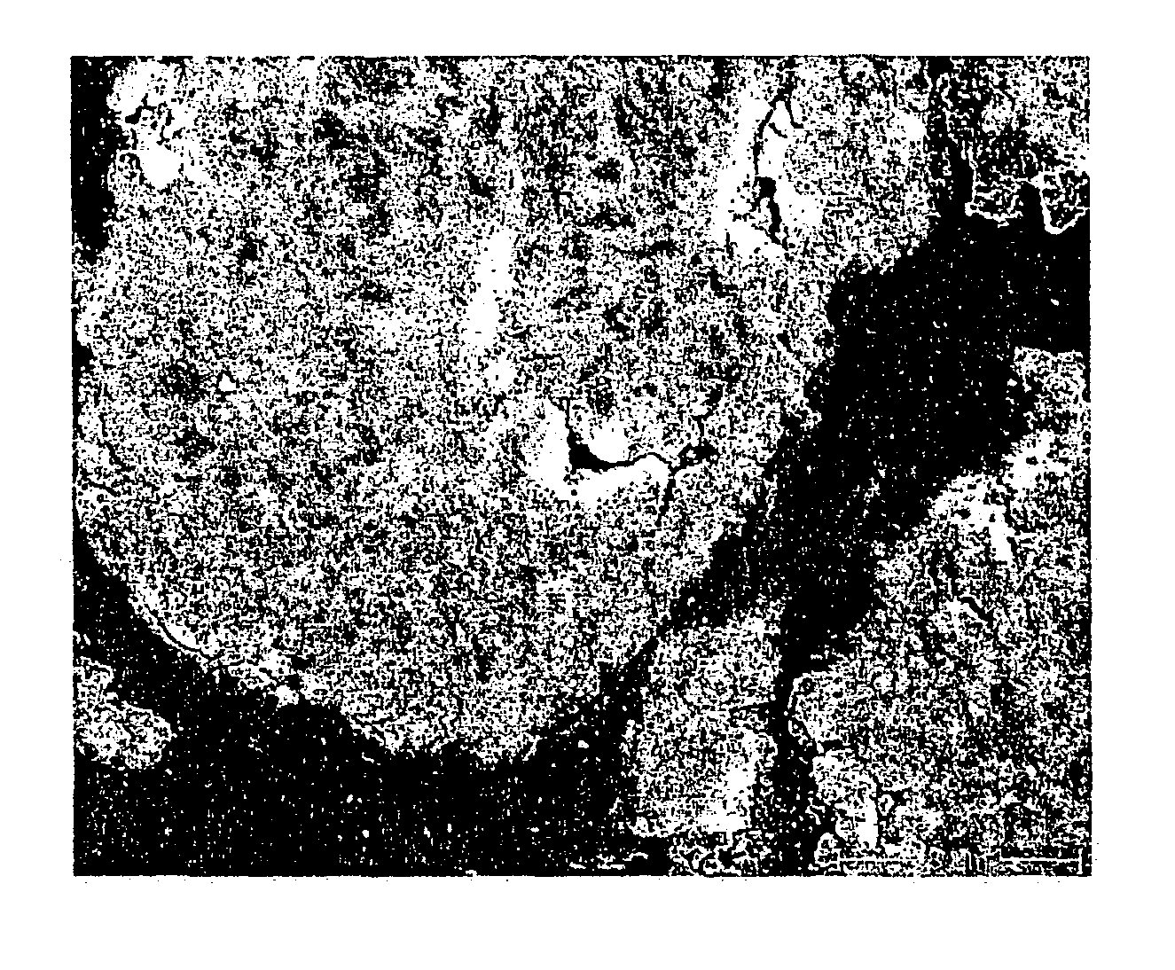
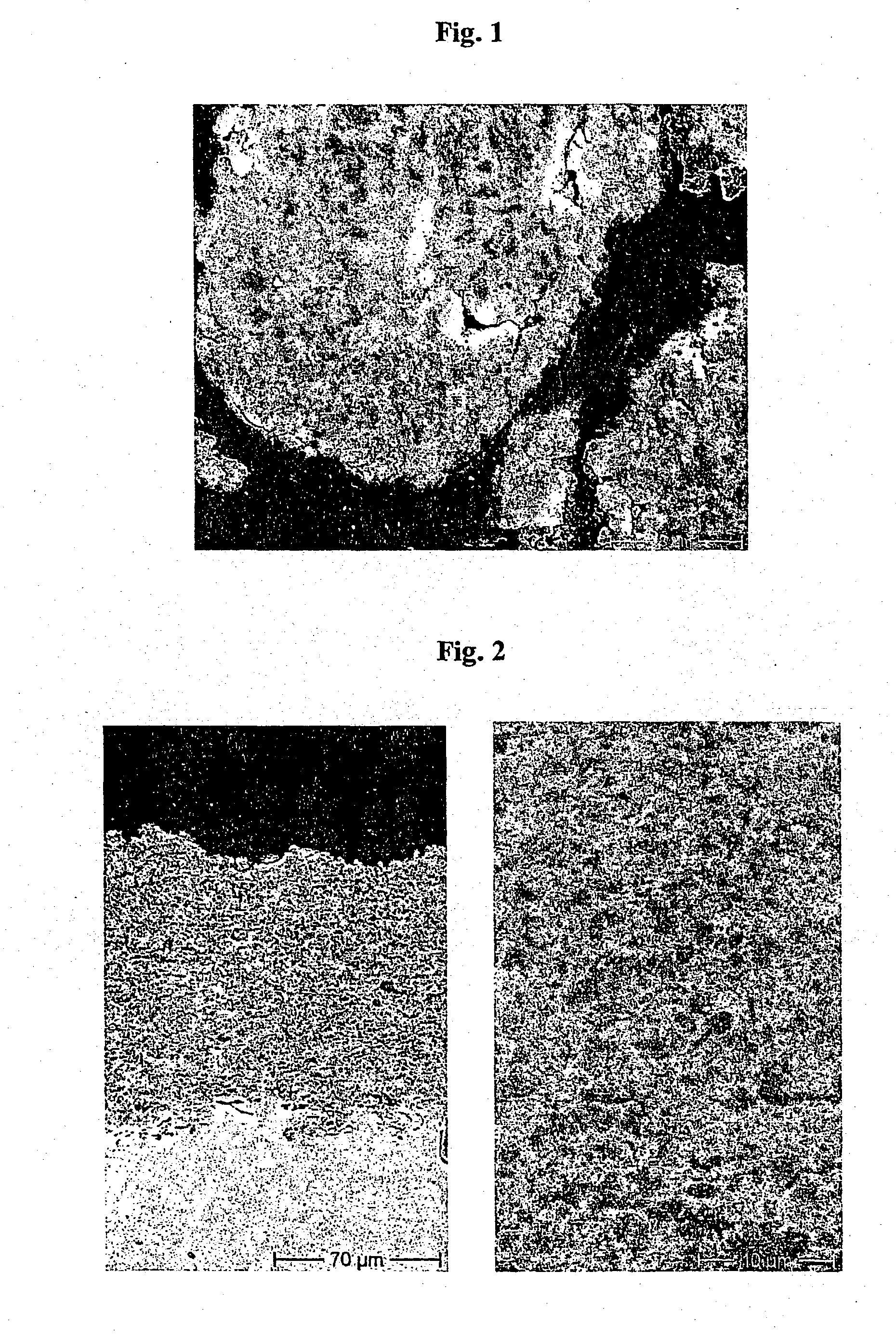
[0038] In Example 1 conventional aluminum oxide spray powder was milled with a conventional spray powder comprised of NiCr in volumetric proportions of 1:1. A powder of extremely finely distributed aluminium oxide phases (gray) resulted after the milling process (FIG. 1: mechanically alloyed powder NiCr-34Al.sub.2O.sub.3). After processing by means of HVOF a very satisfactorily adhering, thick coating was obtained that exhibited the same microscopic structure as the powder (FIG. 2: HVOF sprayed coating exhibits identical microstructures).

Example

EXAMPLE 2

[0039] In Example 2 up to 20% by volume of a powdered solid lubricant was alloyed with the powder of Example 1, which is demonstrably present in the coating after processing using HVOF and clearly improves the frictional behavior of the coating on the piston ring.

Example

EXAMPLE 3

[0040] In Example 3, additional metallic elements such as Mo were added by alloying to the matrix of Example 1, in order to improve the tribological properties of the piston ring coating. The Mo powder is only slightly finely milled in the milling process due to its high viscosity; however, it occurs in the powder and in the coating as a uniformly distributed, excellently imbedded phase. The burn trace behavior of the piston ring coating was demonstrably improved in this way.


PUM

PropertyMeasurementUnit
Percent by massaaaaaaaaaa

Abstract

The invention relates to a wear-resistant coating used for bearing surfaces and flanks of piston rings in internal combustion engines. The wear-resistant inventive coating is obtained by mechanically alloying powders which form a metallic matrix with hard material dispersoids and lubricant material dispersoids. The coating is then thermally applied to the workpieces, especially by means of high velocity oxygen fuel spraying (HVOF). The workpieces coated are bearing surfaces and parts of flanks pertaining to piston rings in internal combustion engines.

Description

[0001] The present invention relates to a wear-resistant coating for use on the bearing surfaces and flanks of piston rings in internal combustion engines. The wear-resistant coating according to the invention is obtained by mechanically alloying powders that form a metallic matrix with hard material dispersoids and lubricant material dispersoids. The coating is then thermally applied to the workpieces, in particular by means of high-velocity flame (HVOF) spraying. The workpieces are the bearing surfaces and flank parts of piston rings in internal combustion engines.[0002] The invention therefore relates particularly to manufacturing and assembly of coatings of mechanically alloyed powders having tribologically optimal properties that are used as the starting materials for coating the piston ring surfaces using thermal methods; for example, by means of thermal spraying and using the coatings obtained using the aforesaid powders on, for instance, piston rings of internal combustion e...

Claims


Application Information

Patent Timeline
IPC IPC(8): F02F5/00B22F1/00C22C1/10C23C4/04C23C4/06F16J9/26
CPCC22C1/1084C23C4/06Y10S428/937Y10T428/12063Y10T428/12014Y10T29/49281Y10T428/12174Y10T428/12826Y10T428/12806Y10T428/12847
Inventor HERBST-DEDERICHS, CHRISTIAN
Owner FEDERAL MOGUL BURSCHEID
Why Eureka
Try Eureka