Decomposition catalyst for nitrous oxide, prcocess for producing the same and process for decomposing nitrous oxide

a technology of nitrous oxide and decomposition catalyst, which is applied in the field of catalysts, can solve the problems of health problems, disadvantages of techniques which may improve the environment in the operating room, and the possibility of destroying the ozone layer, so as to reduce the amount of nox generated and recover the activity

Inactive Publication Date: 2003-09-25
SHOWA DENKO KK
View PDF2 Cites 23 Cited by
  • Summary
  • Abstract
  • Description
  • Claims
  • Application Information

AI Technical Summary

Benefits of technology

0016] The present invention has been made under these circumstances and the object of the present invention is to provide a catalyst for decomposing nitrous oxide contained in a waste anesthetic gas discharged from an operating room. Particularly, the object of the present invention is to provide a catalyst for decomposing nitrous oxide, which cannot be easily affected by a volat

Problems solved by technology

Since 1960, contamination of an operating room by the anesthetic gas and adverse effects of the anesthetic gas on the health of workers in the operating room have been taken as a matter of issue and it is now known that the long-term inhalation of the anesthetic gas leaked out in the operating room causes disorder of the health.
Among volatile anesthetics, volatile anesthetics in particular containing chlorine within the molecule are known to have a possibility of destroying the ozone layer.
From the reasons described above, this technique which may improve the environment within the operating room is disadvantageous from the standpoint

Method used


Image

  • Decomposition catalyst for nitrous oxide, prcocess for producing the same and process for decomposing nitrous oxide
  • Decomposition catalyst for nitrous oxide, prcocess for producing the same and process for decomposing nitrous oxide
  • Decomposition catalyst for nitrous oxide, prcocess for producing the same and process for decomposing nitrous oxide

Examples


example 2

Preparation of Catalyst

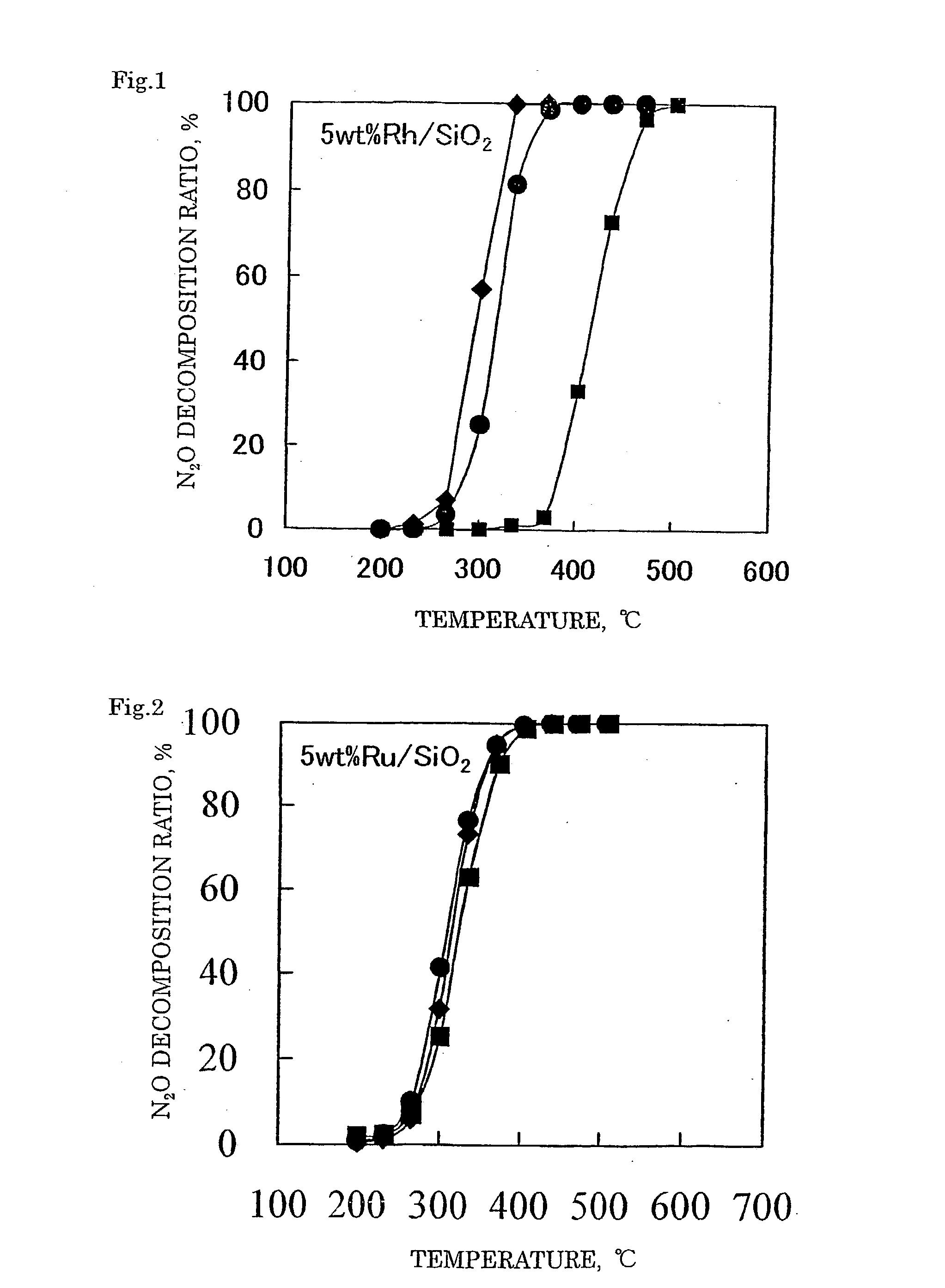
[0113] A catalyst 2 was prepared in the same manner as in Example 1 except for using 0.99 g of a 31.4% ruthenium nitrosyl nitrate solution (Ru(NO)(NO.sub.3).sub.3 aq.). In the catalyst 2 obtained, 5% by mass of ruthenium (Ru) was supported on the silica support.

example 3

Preparation of Catalyst

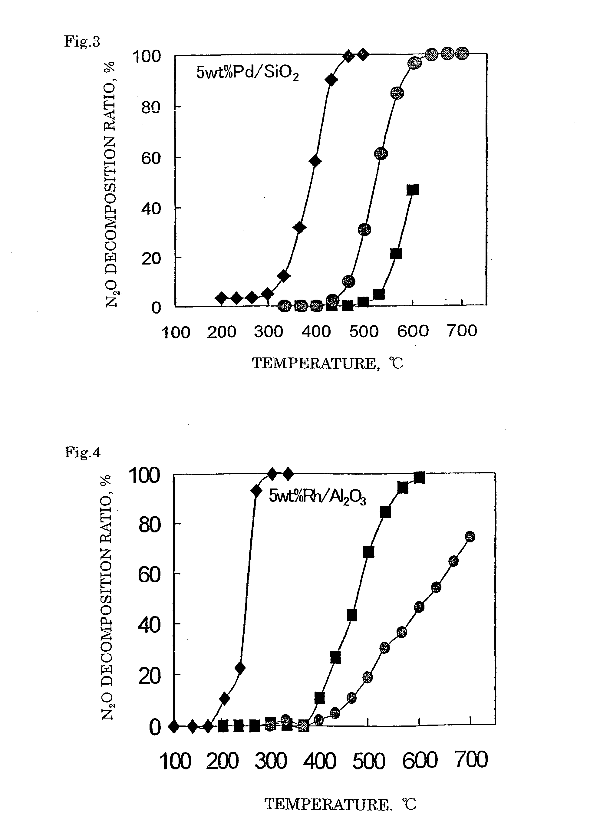
[0114] A catalyst 3 was prepared in the same manner as in Example 1 except for using 0.43 g of a 52.2% palladium nitrate solution (Pd(NO.sub.3).sub.3 aq.). In the catalyst 3 obtained, 5% by mass of palladium (Pd) was supported on the silica support.

example 4

Preparation of Catalyst

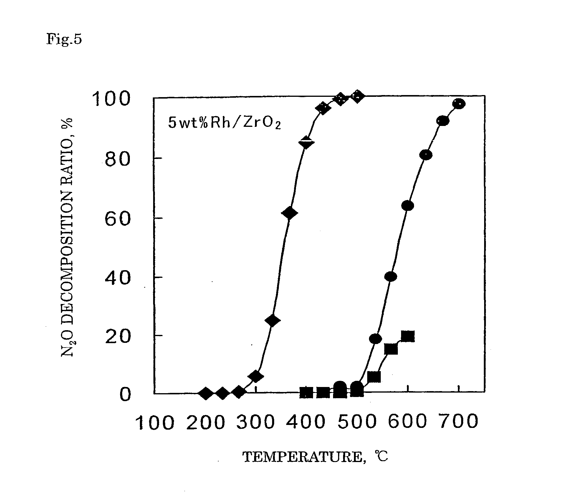
[0115] In 4.94 g of distilled water, 0.208 g of zinc nitrate (Zn(NO.sub.3).sub.2.6H.sub.2O) and 0.54 g of aluminum nitrate (Al(NO.sub.3).sub.3.9H.sub.2O) were dissolved. Thereto, 4.00 g of a silica support was added and after the entire amount was impregnated, the support was dried up in a hot bath at 90.degree. C. The obtained support was dried in air at 120.degree. C. for 12 hours and subsequently calcined in a muffle furnace at 650.degree. C. for 3 hours in an air stream to obtain a spinel crystalline composite oxide silica catalyst precursor where a spinel crystalline composite oxide was supported. With 2.35 g of distilled water, 2.59 g of a 21.4% rhodium nitrate solution (Rh(NO.sub.3).sub.3 aq.) was mixed. Thereto, the spinel crystalline composite oxide silica catalyst precursor was added and after the entire amount was impregnated, the support was dried up in a hot bath at 90.degree. C. The obtained support was dried in air at 120.degree. C. for 12 hours...


PUM

PropertyMeasurementUnit
Percent by massaaaaaaaaaa
Angleaaaaaaaaaa

Abstract

To provide a catalyst obtained by loading at least one noble metal selected from the group consisting of rhodium, ruthenium and palladium on a support selected from silica and silica alumina, and a method for decomposing nitrous oxide using the catalyst thereof. The catalyst for decomposing nitrous oxide of the present invention cannot be easily affected by a volatile anesthetic contained in a waste anesthetic gas, can recover the activity by activation and regeneration even when deteriorated, and can reduce the amount of NOx generated to less than the allowable concentration.

Description

[0001] This application is based on the provisions of 35 U.S.C. Article 111(a) with claiming the benefit of filing dates of U.S. provisional applications Serial No. 60 / 275,107 filed on Mar. 13, 2001, under the provisions of 35 U.S.C. 111(b), pursuant to 35 U.S.C. Article 119(e) (1).[0002] The present invention relates to a catalyst for decomposing nitrous oxide contained in a waste anesthetic gas discharged from an operating room, and also relates to a process for producing the catalyst and a method for decomposing nitrous oxide using the catalyst.[0003] An anesthetic gas contains nitrous oxide and a volatile anesthetic. Since 1960, contamination of an operating room by the anesthetic gas and adverse effects of the anesthetic gas on the health of workers in the operating room have been taken as a matter of issue and it is now known that the long-term inhalation of the anesthetic gas leaked out in the operating room causes disorder of the health. In the U.S.A., the National Institute...

Claims


Application Information

Patent Timeline
IPC IPC(8): B01D53/94B01D53/86B01J23/00B01J23/44B01J23/46B01J23/60B01J23/656B01J23/89B01J37/02
CPCB01D53/86Y02C20/10B01D2255/102B01D2255/20B01D2255/2073B01D2255/20738B01D2255/2092B01D2255/30B01D2257/402B01J23/005B01J23/44B01J23/46B01J23/60B01J23/6562B01J23/8906B01D53/8628
Inventor HOTTA, MASATOSHIFURUSE, YOSHIOATOBE, HITOSHICHAEN, SHIGEHIROTERAOKA, YASUTAKE
Owner SHOWA DENKO KK
Why Eureka
Try Eureka