System and method for providing power factor correction

a technology of power factor and power factor correction, applied in the direction of power conversion systems, climate sustainability, efficient power electronics conversion, etc., can solve the problems of high requirement, energy waste, power factor reduction, etc., and energy loss due to low power factor is usually dissipated, and the requirement carries a significant cos

Inactive Publication Date: 2003-10-30
QSC AUDIO PRODUCTS
View PDF6 Cites 24 Cited by
  • Summary
  • Abstract
  • Description
  • Claims
  • Application Information

AI Technical Summary

Benefits of technology

[0017] In one embodiment the PFC circuit is a modular design capable of being connected to existing power supplies without breaking any connections in the existing power supply. Because the PFC circuit is connected in parallel with the power supply rectifier it does not have to transmit 100% of the power and therefore can use less expensive parts having lower power handling capability than the system as a whole. A further benefit is that the add-on stage is fused so that its failure allows the overall system to continue to function in its original non-PFC mode. The invention may be deployed in parallel with any conventional rectification stage that employs rectifiers that feed a storage capacitor, whether this stage occurs immediately at the AC line input to the system or after the secondary windings of a conventional AC power transformer. Thus the invention can improve the power factor of many existing switched mode power supply ("SMPS") systems and also of simple transformer-coupled linear power supplies. The parallel connection also shows improved efficiency relative to two stage PFC systems because the peak currents do not flow through the PFC circuit.
[0018] Embodiments of the present invention reduce the system cost of a variable consumption system by providing two modes of power factor correction. Below a prescribed power consumption threshold, the line current through the filtered boost converter of the invention is continuous over the AC line voltage cycle and closely tracks the instantaneous AC line voltage, thus providing good power factor correction. Above said threshold power the line cycle current through said boost converter becomes discontinuous, being zero during the peaks of the AC line voltage cycle and being proportional to the instantaneous AC line voltage during non-peak portions of the line voltage waveform. Thus, peak power in excess of the prescribed threshold is supplied by peak currents that flow directly through the host input rectifier, bypassing the PFC circuit. Therefore the power handling components of the subsystem must handle only a fraction of the current and thus can be smaller and less expensive. This attribute makes it a less expensive solution for correcting power factor than prior PFCs and makes it particularly applicable to systems where failsafe behavior is of paramount importance.
[0019] Embodiments of the present invention safely and beneficially handle the condition of very low or zero load power that may occur in variable consumption systems. When load current approaches zero, conventional power factor correction circuits may raise the boost storage capacitor voltage beyond the rating of the capacitor. If overvoltage protection is a feature of the conventional circuit, it may still raise the system voltage to the highest allowed voltage while the system is idling, and this voltage stress can shorten the lifetime of the system. Some embodiments of the present invention overcome this problem by monitoring the magnitude of ripple on the primary reservoir capacitor to sense load current demand. The ripple amplitude is a direct function of load current through the relation dv / dt=i / c. When demand is below a threshold current, the PFC boost action is disabled. Thus the voltage stress upon the primary reservoir capacitor and other system components is reduced when the system is idle or operating at very low power. As soon as sufficient demand is sensed, the PFC circuit is enabled.

Problems solved by technology

The energy lost due to low power factor is usually dissipated in the power distribution system as ohmic losses in the form of waste heat.
In either case, whether higher current harmonics exist or when current and voltage are out of phase and depending on the nature of the electrical device acting as a load, power factor is often decreased and energy is wasted.
Unfortunately, such series connected PFC circuits necessarily carry the full power supplied to the electrical device and that requirement carries a significant cost.
Furthermore, the PFC decreases the overall reliability of such a system because, if for no other reason, they are imperfect like any other device.
When a PFC fails, it may cut power to the electrical device.

Method used


Image

  • System and method for providing power factor correction
  • System and method for providing power factor correction
  • System and method for providing power factor correction

Examples


Embodiment Construction

[0013] The invention will now be described with respect to various embodiments.

[0014] The following description provides specific details for a thorough understanding of, and enabling description for, these embodiments of the invention. However, one skilled in the art will understand that the invention may be practiced without these details. In other instances, well-known structures and functions have not been shown or described in detail to avoid unnecessarily obscuring the description of the embodiments of the invention. For each embodiment, the same reference numbers and acronyms identify elements or acts with the same or similar functionality for ease of understanding and convenience.

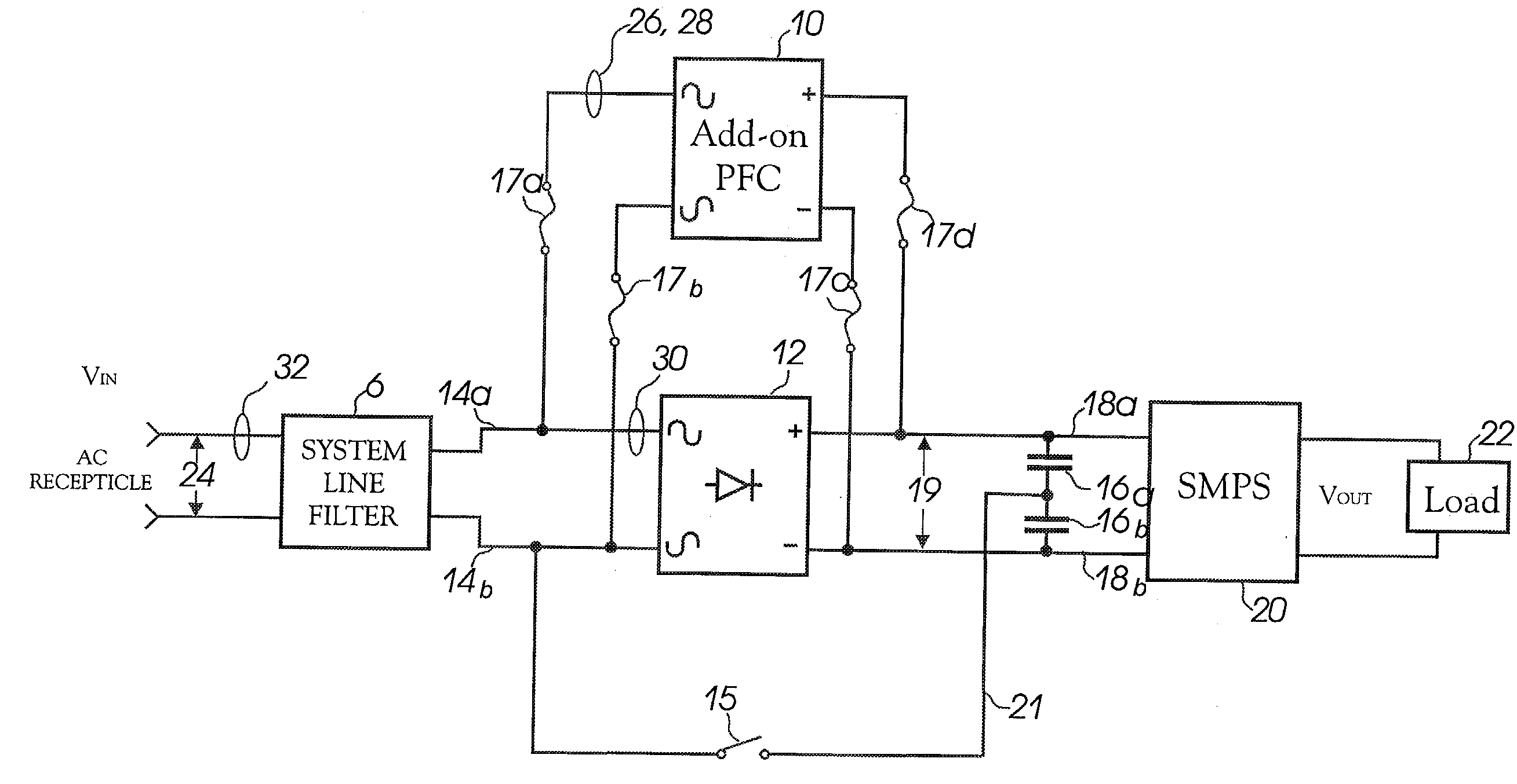
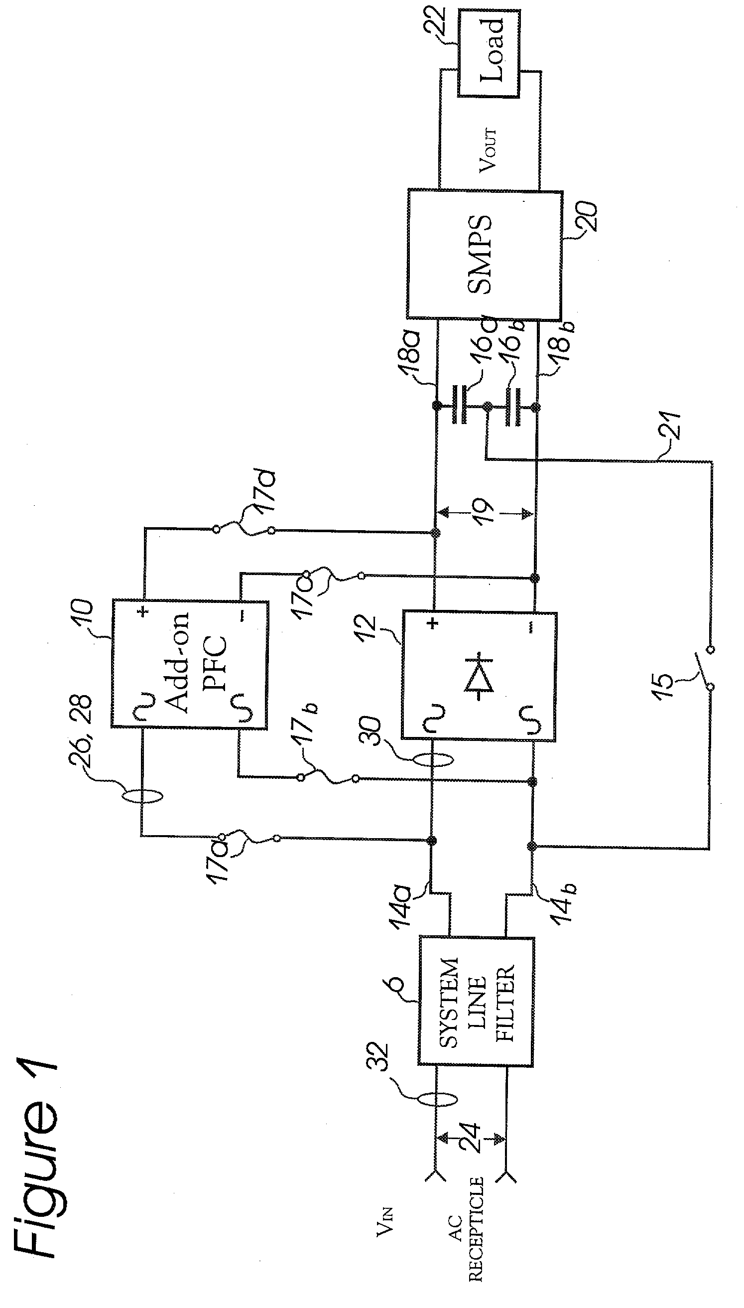
[0015] The problems and disadvantages described above are overcome by embodiments of the invention, which in at least one embodiment provides a novel power factor correction ("PFC") circuit adapted to readily being retrofitted to existing power supplies, provided with new power supplies and / or integ...


PUM


Abstract

In one embodiment, a power factor correction ("PFC") circuit is adapted to readily being retrofitted to existing power supplies, provided with new power supplies and / or integrated into new power supplies. The PFC circuit, unlike prior circuits, is connected in parallel with a power supply rectifier such as an AC-DC rectifier. In one embodiment the rectifier is a bridge rectifier with a rectifier-fed capacitive primary energy reservoir being used as an electrical power source. In one embodiment of the invention, the PFC circuit uses a boost converter governed by a control system to provide a cycle-completion, current-filling PFC mode above a prescribed average power threshold, and a continuous cycle PFC mode below the prescribed average power threshold.

Description

[0001] 1. Technical Field[0002] This invention relates to systems and methods for providing a power factor correction circuit.[0003] 2. Description of the Background[0004] Market forces have created demand for improved electrical product performance and efficiency. One aspect of power efficiency and performance for any given electrical product is known as "Power Factor". Power Factor is a measure the efficiency of electrical power used in an electrical device. One way to measure Power Factor is through the ratio of apparent power consumed by the electrical device (rms voltage times rms current) divided by the actual average power consumed by the electrical device. This ratio can never be greater than one, and is often considerably less. The energy lost due to low power factor is usually dissipated in the power distribution system as ohmic losses in the form of waste heat.[0005] Many electrical products derive their electrical input from alternating current ("AC") sources, such as co...

Claims


Application Information

Patent Timeline
Patent Type & Authority Applications(United States)
IPC IPC(8): H02M1/00H02M1/42
CPCH02M1/4208Y02B70/126H02M1/4225Y02B70/10
Inventor IERYMENKO, PAUL
Owner QSC AUDIO PRODUCTS
Why Eureka
Try Eureka