Rotating cutter bit assembly having hardfaced block and wear washer

Inactive Publication Date: 2003-12-18
KENNAMETAL INC
View PDF19 Cites 50 Cited by
  • Summary
  • Abstract
  • Description
  • Claims
  • Application Information

AI Technical Summary

Benefits of technology

0011] An object of the present invention is to provide an efficient means for protecting holding support blocks, of the type used

Problems solved by technology

During the operation of prior art cutting bits, the support block experienced wear due to the contact between the cutting bit and the support block, as well as the impingement of the debris from the cutting operation.
As the bore and front face of the support block became worn, the support block lost its effectiveness due to deformation and wear of the bore and the front face thereof.
Each one of these conditions impeded the satisfactory rotation of the cutting bit in the support block.
Although providing the capability for free rotation of the cutting-bit results in more uniform wear and extended life of the bit, wear of the bit support block continues to be a problem.
Also, if a bit wears down to the extent that it extends only a short distance out from the face of its support block, more rapid and destructive wear of the support block occurs.
This replacement process is time consuming, and therefore, costly.
F

Method used


Image

  • Rotating cutter bit assembly having hardfaced block and wear washer
  • Rotating cutter bit assembly having hardfaced block and wear washer

Examples


Example

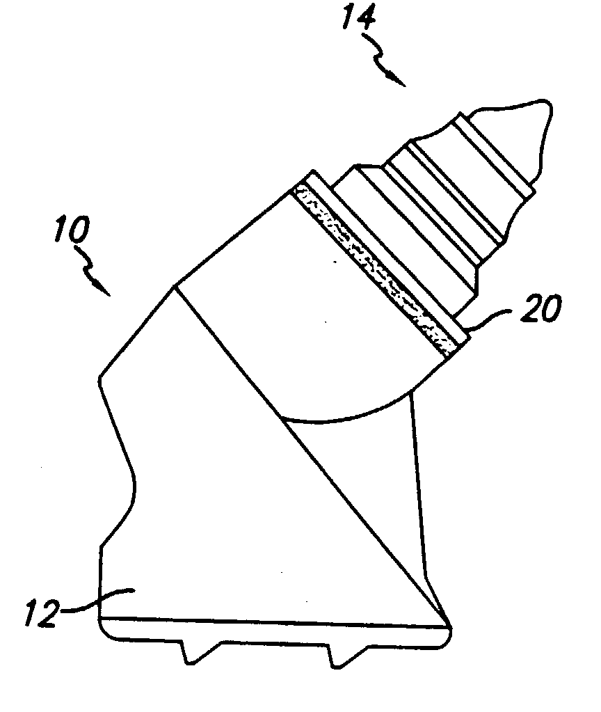
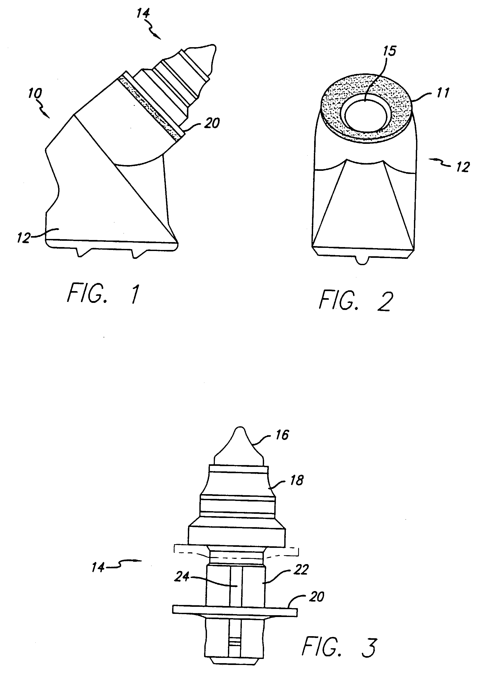
[0018] The cutter block assembly 10 of the present invention is illustrated in FIG. 1. The cutter block assembly 10 includes a holder block 12 and a rotatable cutter bit 14 fixed therein. As best seen in FIG. 2, the top face 11 of the block has a hardfacing material deposited thereon represented by the speckled / shaded grit.

[0019] The cutter bit assembly is best shown in FIG. 3. The cutter bit assembly includes a cutter body having an integral conical head 18 and shaft 24, cutting tip 16, a retainer 22 and a bearing washer 20. The cutter bit assembly 14 is first inserted and manually knocked into the bore 15 of the holder block, typically with a hammer. The retainer sleeve 22 is made from Spring Steel that is held in a compressed loaded position by the holding washer 20 as shown in FIG. 3. In the compressed loaded position the external diameter of the sleeve is less than the internal diameter of the bore. When the cutter bit assembly 14 is hammered into the bore 15 of the holder bloc...


PUM

PropertyMeasurementUnit
Fractionaaaaaaaaaa
Fractionaaaaaaaaaa
Fractionaaaaaaaaaa

Abstract

A rotatable cutting bit, and rotatable cutting bit-bit holder assembly and washer that have increased wear resistance characteristics. The assembly incorporates a new holding washer design that has improved wear resistant characteristics between the cutter bit and top surface of the bit holder during operation. The cutter bit assembly includes a bit holder having a top surface, a generally flat washer, the top surface includes a top face forming a bearing surface for the cutting bit to enhance rotation of the cutter bit. The wear rate caused by the relative rotation between the rear face of the washer and top surface of the block face is reduced in the present invention. The top surface of the bit holder is hardfaced to limit and reduce wear. The improved wear resistance properties of the invention reduce the amount of necessary maintenance of rotary drums in the field resulting in reduce downtime and increase productivity.

Description

[0001] This application is a nonprovisional application of U.S. Provisional Application No. 60 / 385,683, filed Jun. 4, 2002.FIELD OF THE INVENTION[0002] This invention relates to an article for improving the efficiency of operation of carbide-tipped cutting bits utilized in rotary machines adapted for pulverizing concrete and asphalt roadways and similar surfaces. More particularly, the invention relates to articles for improving the cutting action of rotatable carbide bits, and for protecting the support blocks in which the bits are mounted.[0003] In the prior art, cutting bits are mounted to be rotatable about the central axis of the cutting bit mounted in a support block. The rotation of the cutting bit provides for uniform wear of the cutting bit improving the effective life of the cutting tool. The rotatable cutting bits have a flange bottom face that bears against the top face of the support block.[0004] During the operation of prior art cutting bits, the support block experien...

Claims


Application Information

Patent Timeline
IPC IPC(8): B28D1/18E21C35/183
CPCE21C35/183B28D1/188
Inventor MONDY, MICHAEL C.WEBB, KIRK E.
Owner KENNAMETAL INC
Why Eureka
Try Eureka