Error detection/correction code which detects and corrects memory module/transmitter circuit failure

a technology of error detection and correction code, which is applied in error detection/correction, instruments, computing, etc., can solve problems such as faulty components, faulty memory chips, and common source of errors in electrical systems

Active Publication Date: 2004-01-01
ORACLE INT CORP
View PDF64 Cites 72 Cited by
  • Summary
  • Abstract
  • Description
  • Claims
  • Application Information

AI Technical Summary

Problems solved by technology

Component failures are a common source of error in electrical systems.
Faulty components may include faulty memory chips or faulty data paths provided between devices of a system.
Faulty data paths can result from, for example, faulty pins, faulty data traces, or faulty wires.
Additionally, memory modules, which may contain multiple memory chips, may fail.
Circuitry which drives the data paths may also fail.
Another source of error in electrical systems may be so-called "soft" or "transient errors".
Transient memory errors may be an error caused by the occurrence of an event, rather than a defect in the memory circuitry itself.
Transient memory errors may occur due to, for example, random alpha particles striking the memory circuit.
Transient communication errors may occur due to noise on the data paths, inaccurate sampling of the data due to clock drift, etc.
On the other hand, "hard" or "persistent" errors may occur due to component failure.
If the parity doesn't match the accessed set of data bits, then an error is detected.

Method used


Image

  • Error detection/correction code which detects and corrects memory module/transmitter circuit failure
  • Error detection/correction code which detects and corrects memory module/transmitter circuit failure
  • Error detection/correction code which detects and corrects memory module/transmitter circuit failure

Examples


first embodiment

[0060] FIG. 4 illustrates a code word with a remapping of a column corresponding to a memory device that has failed. Other embodiments are possible and contemplated. In FIG. 4, a column CF is shown which corresponds to a failed memory device. The column CF is remapped to the column co, which previously stores the auxiliary check bits in this embodiment. The inner check bits are stored in column c.sub.1, and the inner check bit duals are stored in a portion of the column c.sub.2. The outer check bits are stored in two or more columns ending in c.sub.m, where the number of columns is equal to the number of memory devices in the memory bank and on a given memory module. The outer check bits may be an exclusive OR of the bits in the same position (row and column) within each of the other memory modules. Thus, the outer check bits include enough information to identify failing rows, and the auxiliary check bits may be redundant, in such embodiments.

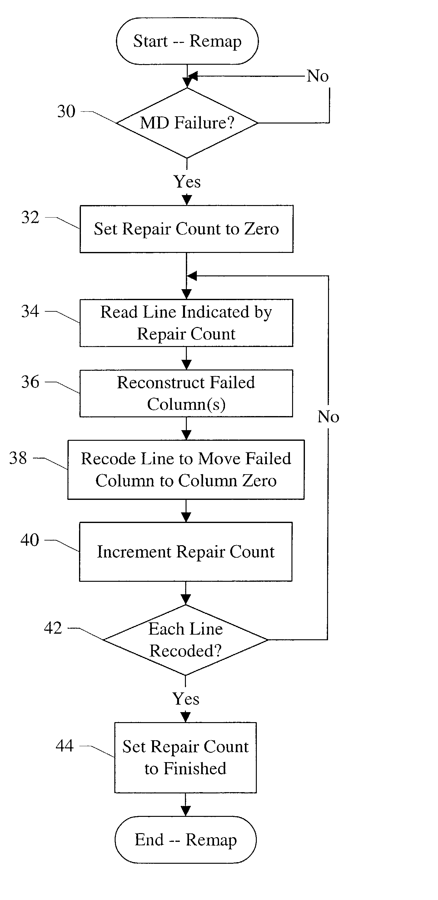
[0061] FIG. 5 is a flowchart illustrati...

second embodiment

[0069] FIG. 6 illustrates a code word with a remapping of a failed memory device and a subsequent detection and correction of a second failed memory device. Other embodiments are possible and contemplated. The embodiment of FIG. 6 may thus detect and correct, including remapping, a first memory device failure followed by detecting and correcting a second memory device failure. Additionally, single bit error correction (and double bit error detection, following the remapping) may be performed in this embodiment.

[0070] In the embodiment of FIG. 6, a column CN stores some of the metadata portion of the data supplied for reads and writes. Particularly, the metadata stored in the column CN is logically not used by the producers and consumers of the data. The producers of the data may set the unused metadata to a constant value (e.g. binary zeros, binary ones, or any constant combination of binary zeros and ones). Accordingly, the first failed memory device (corresponding to column C.sub....

case 0

[0101] Encoding #1

[0102] Column 1=Inner Check Bits.sub.0 7 XOR g.sub.0(Inner Check Bits.sub.8 11)

[0103] Column 2.sub.0 3=f.sub.0(Inner Check Bits.sub.8 11)

[0104] Column 2.sub.4 7=Data.sub.--2.sub.4 7

[0105] Column 3=Data.sub.--3

[0106] Column 0=auxiliary check bits


PUM


Abstract

A memory controller may include a check bit encoder circuit and a check / correct circuit. The check bit encoder circuit is coupled to receive a data block to be written to memory, where the memory includes a plurality of memory devices arranged on a plurality of memory modules. Each of the plurality of memory modules includes a plurality of the plurality of memory devices. The check bit encoder circuit is configured to encode the data block with a plurality of check bits to generate an encoded data block. The plurality of check bits are defined to provide at least detection of a failure of one of the plurality of memory modules. The check / correct circuit is coupled to receive the encoded data block from the memory, and is configured to detect the failure of one of the plurality of memory modules responsive to decoding the encoded data block.

Description

[0001] 1. Field of the Invention[0002] This invention is related to the field of error checking and correction in memory systems and communication systems.[0003] 2. Description of the Related Art[0004] Error codes are commonly used in electronic systems to detect and correct data errors, such as transmission errors or storage errors. For example, error codes may be used to detect and correct errors in data transmitted via any transmission medium (e.g. conductors and / or transmitting devices between chips in an electronic system, a network connect, a telephone line, a radio transmitter, etc.). Error codes may additionally be used to detect and correct errors associated with data stored in the memory of computer systems. One common use of error codes is to detect and correct errors of data transmitted on a data bus of a computer system. In such systems, error correction bits, or check bits, may be generated for the data prior to its transfer or storage. When the data is received or ret...

Claims


Application Information

Patent Timeline
Patent Type & Authority Applications(United States)
IPC IPC(8): G11C29/42
CPCG11C29/42
Inventor CYPHER, ROBERT E.
Owner ORACLE INT CORP
Why Eureka
Try Eureka