
Transmission error concealment in an audio signal

a technology of audio signal and transmission error, applied in the field of transmission error concealment in audio signal, can solve the problems of troublesome artifacts, introduction of audible spectral distortion,

Inactive Publication Date: 2004-01-15
FRANCE TELECOM SA
View PDF8 Cites 76 Cited by
  • Summary
  • Abstract
  • Description
  • Claims
  • Application Information

AI Technical Summary

Benefits of technology

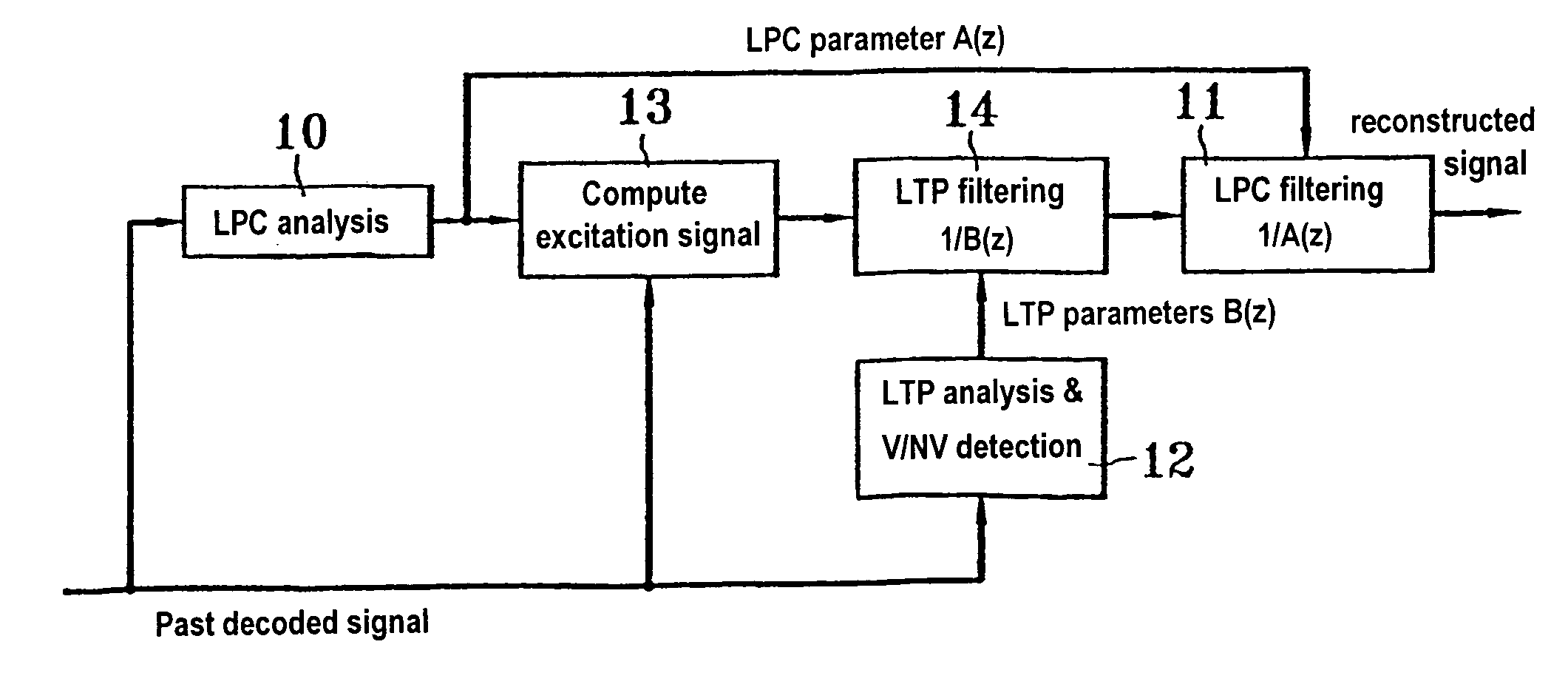
[0063] This spectral envelope is computed in the form of an LPC filter [RABINER] [KLEIJN]. Analysis is performed by conventional methods ([KLEIJN]) after windowing samples stored in a valid period. Specifically, LPC analysis is performed (step 10) to obtain the parameters of a filter A(z), whose inverse is used for LPC filtering (step 11). Since the coefficients as computed in this way are not for transmission, this can be implemented using high order analysis, thus making it possible to achieve good performance on music signals.
[0066] When the signal is declared to be voiced, the parameters that enable a long-term synthesis filter to be generated are computed, also referred to as an LTP filter ([KLEIJN]) (FIG. 3: LTP analysis, with the computed inverse LTP filter being defined by B(Z)). Such a filter is generally represented by a gain and by a period corresponding to the fundamental period. The precision of the filter can be improved by using fractional pitch or by using a multi-coefficient structure [KROON].
[0081] When the signal is not voiced, or is weakly voiced, the residual signal used for generating excitation is processed so as to eliminate amplitude peaks that are significantly above the average.
[0095] When the coding structure makes it possible, it is also possible to limit the above procedure to an intermediate zone at the beginning of the valid data period following an erased period, with the updating procedure then being additional to the decoding operation.

Problems solved by technology

The drawbacks of the method proposed lie in the introduction of audible spectral distortion (a "synthetic" voice, parasitic resonances, .
. . ), due specifically to the use of poorly-controlled long-term synthesis filters (a single harmonic component in voiced sounds, excitation signal generation restricted to the use of portions of the past residual signal).
In addition, energy control is performed in [COMBESCURE] at excitation signal level, with the energy target for said signal being kept constant throughout the duration of the erasure, and that also gives rise to troublesome artifacts.

Method used


Image

  • Transmission error concealment in an audio signal
  • Transmission error concealment in an audio signal
  • Transmission error concealment in an audio signal

Examples


Embodiment Construction

5.1 The Principles of a Possible Embodiment

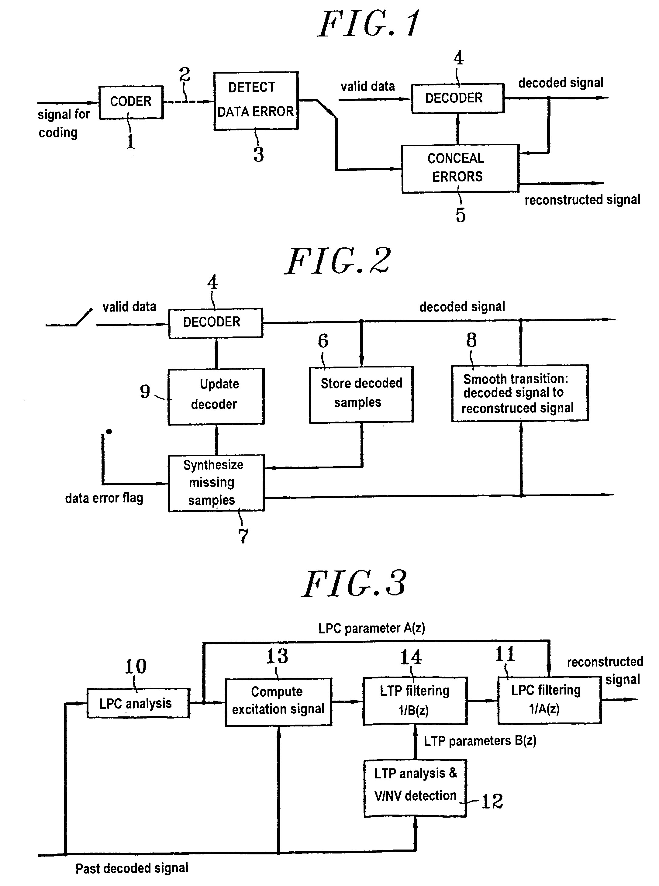
[0053] FIG. 1 shows apparatus for coding and decoding a digital audio signal, the apparatus comprising a coder 1, a transmission channel 2, a module 3 serving to detect that transmitted data has been lost or is highly erroneous, a decoder 4, and a module 5 for concealing errors or lost packets in a possible implementation of the invention.

[0054] It should be observed that in addition to receiving information that data has been erased, the module 5 also receives the decoded signal during valid periods and it forwards signals to the decoder that are used for updating it.

[0055] More precisely, the processing implemented by the module 5 relies on:

[0056] 1. storing samples as decoded while the transmitted data is valid (process 6):

[0057] 2. during an erased data block, synthesizing samples corresponding to the lost data (process 7);

[0058] 3. once transmission is reestablished, smoothing between the synthesized samples produced during the erased ...


PUM


Abstract

A method of concealing transmission error in a digital audio signal in which a signal that has been decoded after transmission is received, the samples decoded while the transmitted data is valid are stored, at least one short-term prediction operator and one long-term prediction operator are estimated as a function of stored valid samples, and any missing or erroneous samples in the decoder signal are generated using the operators estimated in this way, the method being characterized in that the energy of the synthesized signal as generated in this way is controlled by means of a gain that is computed and adapted sample by sample.

Description

1. TECHNICAL FIELD[0001] The present invention relates to techniques for concealing consecutive transmission errors in transmission systems using digital coding of any type on a speech and / or sound signal.[0002] It is conventional to distinguish between two major categories of coder:[0003] "time" coders which compress digitized signal samples on a sample-by-sample basis (as applies to pulse code modulation (PCM) and to adaptive differential PCM (ADPCM) [DAUMER] [MAITRE], for example); and[0004] parametric coders which analyze successive frames of signal samples for coding in order to extract from each frame a certain number of parameters which are then coded and transmitted (as applies to vocoders [TREMAIN], IMBE coders [HARDWICK], or transform coders [BRANDENBURG]).[0005] There also exist intermediate categories which associate the coding of representative parameters as performed by parametric coders, with the coding of a residual time waveform. To simplify, such coders can be incl...

Claims


Application Information

Patent Timeline
IPC IPC(8): G10L13/00G10L19/005
CPCG10L19/005
Inventor KOVESI, BALAZSMASSALOUX, DOMINIQUEDELEAM, DAVID
Owner FRANCE TELECOM SA
Learn More