Method for monitoring a coolant circuit of an internal combustion engine

a technology of internal combustion engine and coolant circuit, which is applied in the direction of machines/engines, mechanical equipment, instruments, etc., can solve the problems of inability to analyze the interrelationship between these parameters, and the inability to calculate analytically the temperature of the components, etc., and achieve the effect of poor emissions rang

Inactive Publication Date: 2004-01-22
ROBERT BOSCH GMBH
View PDF3 Cites 18 Cited by
  • Summary
  • Abstract
  • Description
  • Claims
  • Application Information

AI Technical Summary

Benefits of technology

0005] According to the invention, the control unit predetermines a permissible upper and lower deviation of a reference parameter from a desired value based on operating parameters of the internal combustion engine and with the aid of deviation characteristic fields. The control unit compares these deviations with a difference between a desired value and an actual value of the reference parameter, and the actual value is determined from parameters of the volumetric flow of cooling fluid, possibly with the aid of characteristic fields.
0006] The invention is based on the knowledge that the emissions of an internal combustion engine are influenced by the combustion and this combustion in turn is influenced by the temperatures of critical components, in particular of the combustion chamber wall, which in reciprocating piston internal combustion engines is chiefly comprised of the inner wall of the cylinders and the cylinder head. If the relationship between the component temperature and the emissions as a function of an operating point of the engine is known and lies within a characteristic field, then the diagnosis and monitoring are executed by monitoring the component temperatures. In this case, the temperature of the component itself or of a parameter associated with this temperature can be used as a reference parameter. The temperatures of the selected reference component in a given internal combustion engine at a particular operating point are determined by means of the temperature and the volumetric flow of the cooling fluid. According to the invention, therefore, the temperature and the volumetric flow of the cooling fluid are used to monitor the cooling fluid circuit.
0007] In one embodiment of the invention, in which the temperature of the reference component itself--e.g. of the wall of a cylinder, cylinder block, or cylinder head--is used as a reference parameter, an actual value of the temperature of the reference component is determined with the aid of a temperature characteristic field, a cooling fluid temperature preferably measured at the outlet of the internal combustion engine, and an actual value of the volumetric flow. In this case, the actual value of the volumetric flow is inferred from a differential pressure at the throttle restriction in the main flow of the cooling fluid and from the trigger signal of the cooling fluid pump. The difference is calculated between the actual value and a desired value of the temperature of the reference component, which is determined from the speed and load of the internal combustion engine with the aid of an additional temperature characteristic field, and this difference is compared to a permissible lower and upper deviation of the temperature of the reference component. If the result of the comparison is greater than or equal to one, then an output signal is generated that indicates a malfunction in the cooling fluid pump or in the cooling fluid circuit, for example due to the fluid pump or a regulating valve being jammed, or due to a hose being crushed.
0008] When heated, the cooling fluid temperature is either kept constant or varies within a permissible range. The cooling f...

Problems solved by technology

The interrelationships among these parameters and the temperature of ...

Method used


Image

  • Method for monitoring a coolant circuit of an internal combustion engine
  • Method for monitoring a coolant circuit of an internal combustion engine
  • Method for monitoring a coolant circuit of an internal combustion engine

Examples


Embodiment Construction

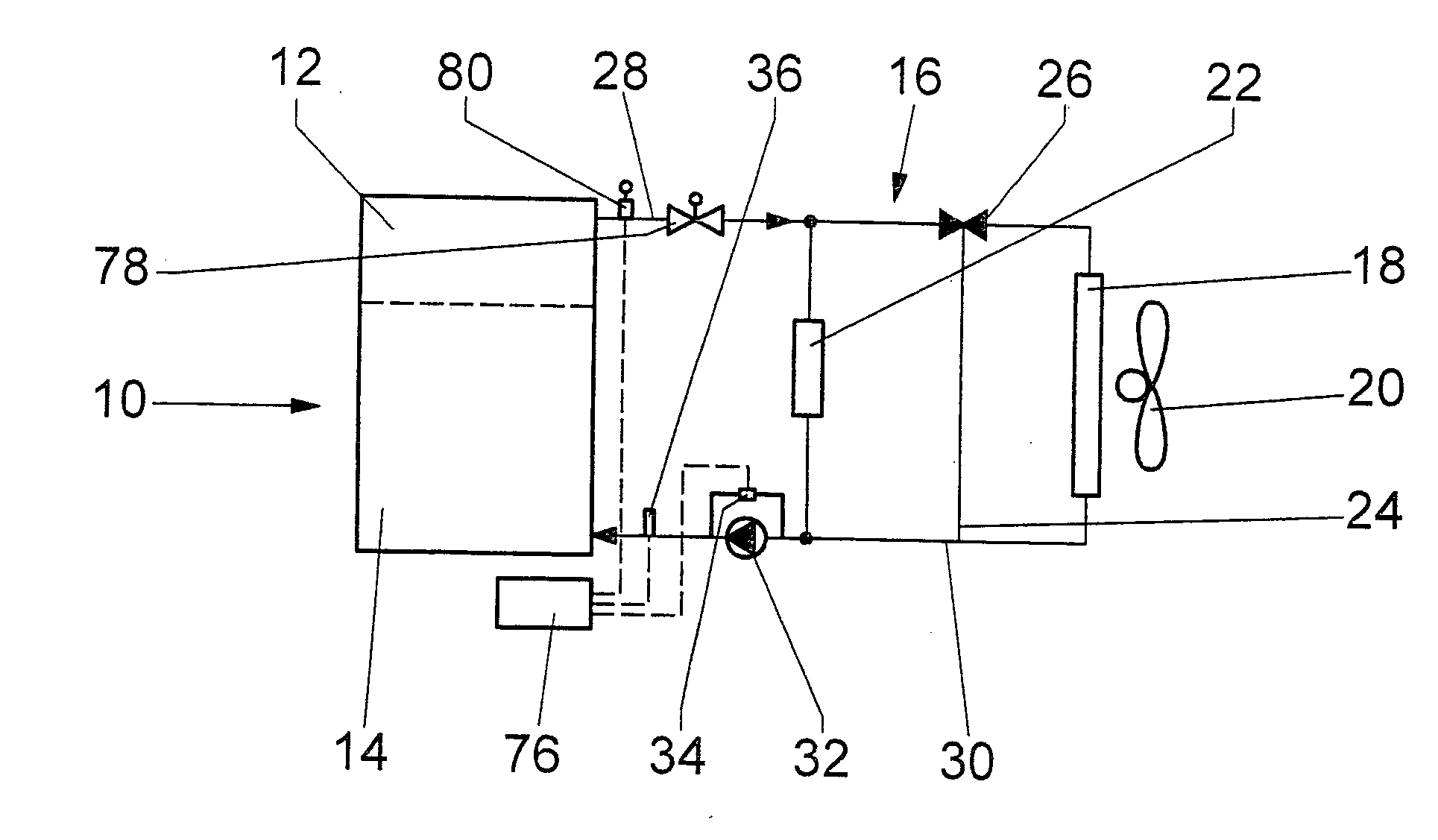
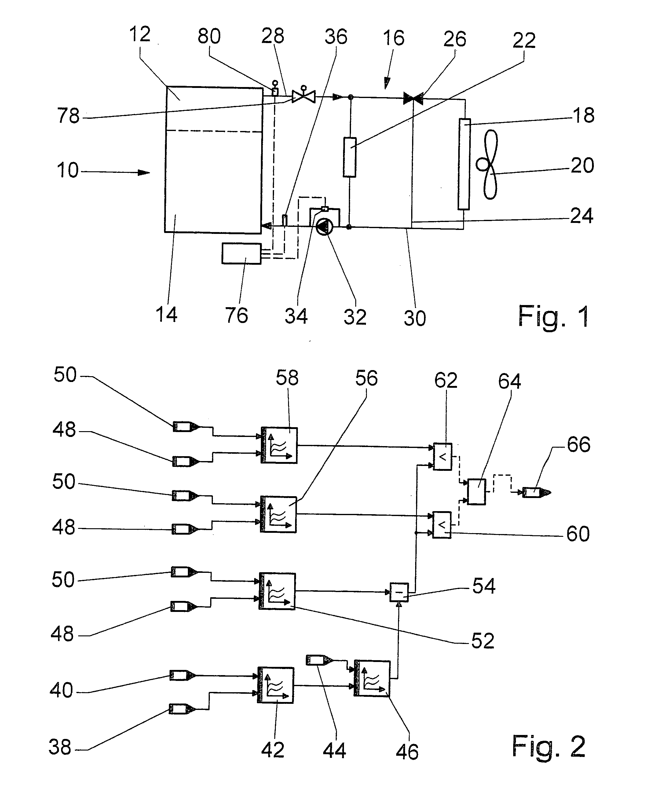
[0016] An internal combustion engine 10 includes a cylinder head 12 and a cylinder block 14, which are connected to a cooling fluid circuit 16. The flow direction of the cooling fluid in the cooling fluid circuit 16 is indicated with arrows. A cooling fluid pump 32 feeds the cooling fluid from an intake line 30, through the cylinder block 14 and the cylinder head 12, and into a return line 28. A radiator 18 that cooperates with a fan 20 is connected between this return line 28 and the intake line 30. A bypass line 24 and a heating system heat exchanger 22 are provided parallel to the radiator 18 and a regulating valve 26 controls the flow through the radiator 18 and the bypass line 24.

[0017] Parallel to the cooling fluid pump 32, a differential pressure sensor 34 is provided, which detects the differential pressure between the suction side and the pressure side of the cooling fluid pump 32. Alternatively or in addition to the differential pressure sensor 34, a pressure sensor 36 is ...


PUM


Abstract

The invention is based on a method for monitoring a cooling fluid circuit (16) of an internal combustion engine (10), with at least one heat exchanger (18, 22), a regulating valve (26), a cooling fluid pump (32), and an electronic control unit (76). The invention proposes that the control unit (76) predetermine a permissible upper and lower deviation of a reference parameter from a desired value, based on operating parameters of the internal combustion engine (10) and with the aid of deviation characteristic fields (56, 58), and that it compare these permissible upper and lower deviations to a difference between a desired value and an actual value of the reference parameter, wherein the actual value is determined based on parameters of the volumetric flow of the cooling fluid, possibly with the aid of characteristic fields (42, 46, 74).

Description

PRIOR ART[0001] The invention is based on a method for monitoring a cooling fluid circuit in an internal combustion engine according to the preamble to claim 1.[0002] In modern reciprocating piston internal combustion engines for motor vehicles, the heat transmitted to a cylinder head and cylinder block through a wall of a combustion chamber is essentially dissipated by means of a cooling fluid. The cooling fluid is circulated by means of a pump, which is as a rule mechanically driven by the internal combustion engine. There are also known embodiments in which a controllable electric motor is used as a pump drive unit. A regulating valve conveys the cooling fluid through a radiator or through a bypass line, which is provided parallel to the radiator. In addition to the radiator, a heating system heat exchanger for the passenger compartment is also connected to the cooling fluid circuit. A desired temperature of the cooling fluid, possibly controlled by means of a characteristic fiel...

Claims


Application Information

Patent Timeline
IPC IPC(8): F01P7/16F01P11/14F01P11/16
CPCF01P7/164F01P7/167F01P11/14F01P11/16F01P2025/33F01P2025/04F01P2025/06F01P2025/31F01P2025/32F01P2023/08F01P7/12
Inventor HERYNEK, ROLANDVOLLMER, MARTIN
Owner ROBERT BOSCH GMBH
Why Eureka
Try Eureka