
Magnetically erecorded data reproduction apparatus and method

Inactive Publication Date: 2004-02-05
SONY CORP
View PDF13 Cites 4 Cited by
  • Summary
  • Abstract
  • Description
  • Claims
  • Application Information

AI Technical Summary

Benefits of technology

[0015] The object of the present invention is to eliminate the effect of conceivable noise caused by the so-called thermal asperity (TA noise) and to prevent increases in the error rate of reproduction signals due to the TA noise effect, thereby preventing the occurrence of problems in equipment. According to the present invention, there is provided an apparatus for reproducing magnetically recorded data and method thereof, wherein the output signal from the magnetoresistive head is extracted through a predetermined high-pass filter and then low-frequency component correction is performed on the extracted signals.

Problems solved by technology

When, however, this type of MR head is used to reproduce data recorded on, for example, magnetic tape, a problem of the so-called thermal asperity noise (hereinafter referred to as TA noise) occurs.
Namely, TA noise is a specific problem when using the MR head to reproduce recorded data.
As a result, when such a surge occurs, the error rate of the reproduction signal will increase and therefore problems such as picture freezing, audio discontinuity or others will occur in equipment such as a digital VTR.

Method used


Image

  • Magnetically erecorded data reproduction apparatus and method
  • Magnetically erecorded data reproduction apparatus and method
  • Magnetically erecorded data reproduction apparatus and method

Examples


Embodiment Construction

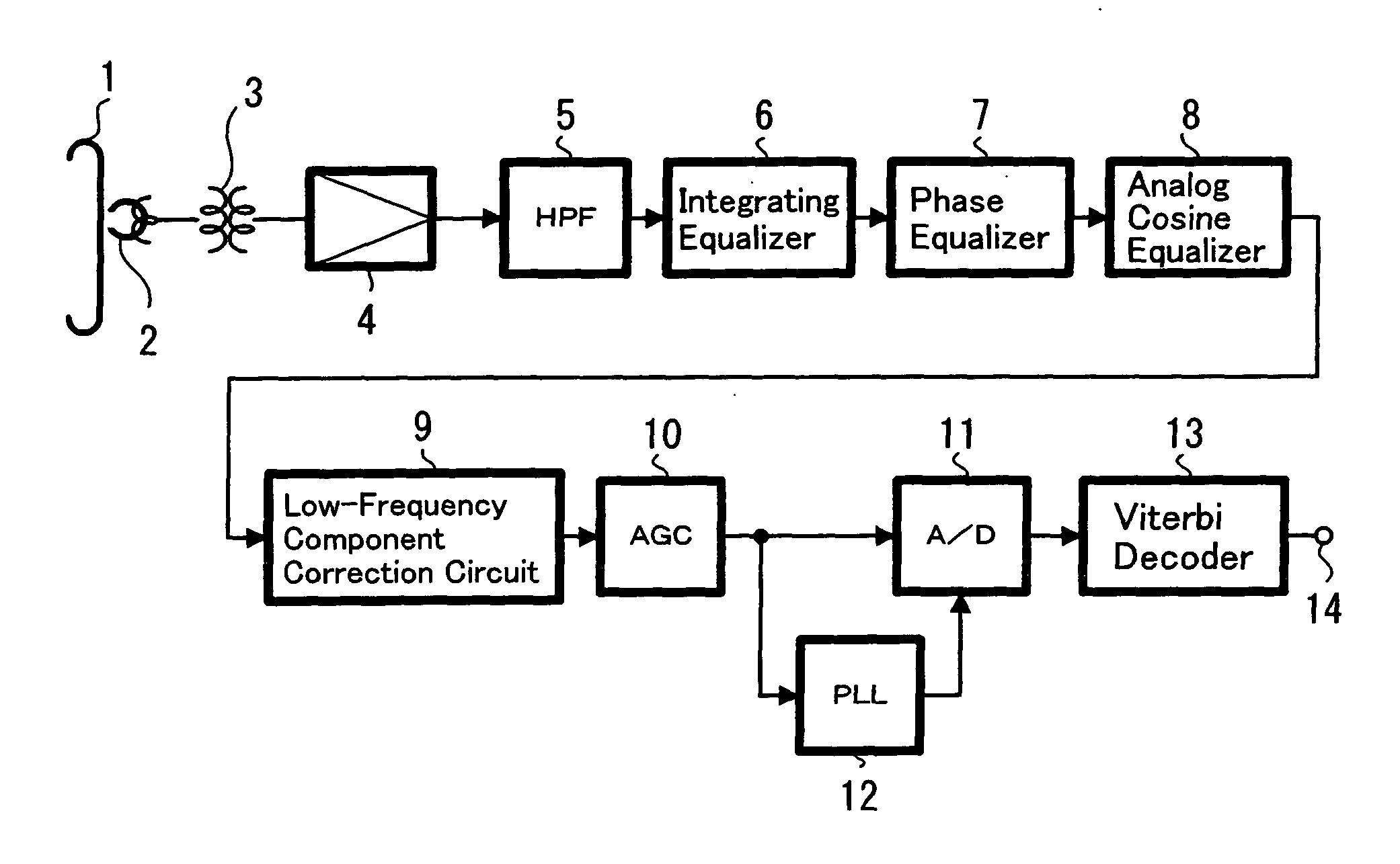
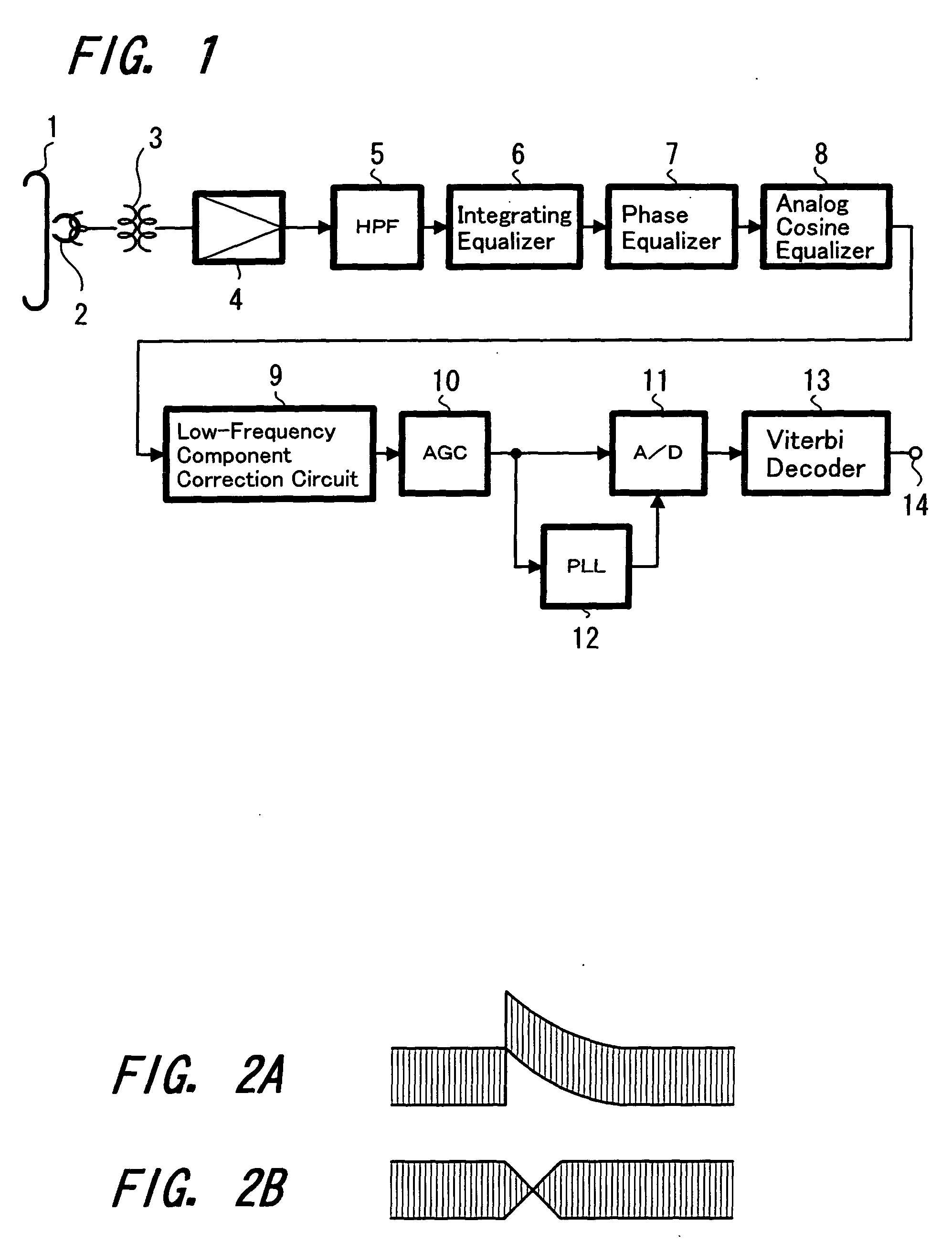
[0026] Referring to the figures, hereinafter the present invention is described, and FIG. 1 is a block diagram showing the configuration of an embodiment of the magnetically recorded data reproduction apparatus to which the present invention is applied.

[0027] In FIG. 1, data recorded on, for example, magnetic tape 1 are reproduced by a magnetoresistive head 2 (hereinafter referred to as MR head) and the reproduction signal is extracted to the outside of, for example, a rotating drum (not shown in the figure) through a rotary transformer 3 and then supplied to a reproduction amplifier 4. Further, the signal from the reproduction amplifier 4 is supplied to a high-pass filter 5 (hereinafter referred to as HPF) and the frequency component of, for example, 1 MHz or lower, is cut off.

[0028] Hereupon, when noise due to, for example, thermal asperity (TA noise), has occurred, a signal with a large DC component such as shown, for example, in FIG. 2A is extracted from the reproduction amplifi...


PUM


Abstract

The present invention relates to a magnetically recorded data reproduction apparatus which reproduces magnetically recorded data using a magnetoresistive head and method thereof. In this invention the recorded data are reproduced by a magnetoresistive head 2 and supplied to a reproduction amplifier 4. The signal from the reproduction amplifier 4 is then supplied to a high-pass filter 5 and a frequency component of, for example, 1 MHz or lower, is cut off. The signal from the HPF 5 is supplied to an integrating equalizer 6, a phase equalizer 7 and an analog cosine equalizer 8. The signal from the equalizer 8 is supplied to an AGC amplifier 10 through a low-frequency component correction circuit 9. The signal from the AGC amplifier 10 is supplied to an A / D converter 11. Further, the signal from the AGC amplifier 10 is supplied to the digital PLL circuit 12 and the extracted clock signal is supplied to the A / D converter 11. The digitized signal is then supplied to, for example, a Viterbi decoder 13 and the decoded signal is obtained at an output terminal 14. Thus, the effect of noise due to the so-called thermal asperity (TA noise) is removed, thereby preventing increases in the error rate of the reproduction signals due to the effect of TA noise and the occurrence of problems in equipment.

Description

[0001] The present invention relates to an apparatus for reproducing magnetically recorded data using a magnetoresistive head, and a method thereof. Particularly, the present invention relates to an apparatus for reproducing magnetically recorded data and a method thereof in which the effect of thermal asperity noise specific to magnetoresistive heads is made to reduce.[0002] The configuration, for example, shown in FIG. 5 has been used in an apparatus for reproducing magnetically recorded data using magneto-resistive heads.[0003] Specifically, in FIG. 5 data recorded on, for example, magnetic tape 51 are reproduced by a magnetoresistive head (hereinafter referred to as MR head) 52. The reproduction signal is extracted to the outside of, for example, a rotating drum (not shown in the figure) through a rotary transformer 53 and then supplied to a reproduction amplifier 54.[0004] Hereupon, a low-frequency component of the extracted signal has been cut off through the rotary transforme...

Claims


Application Information

Patent Timeline
IPC IPC(8): G11B5/027G11B5/00G11B5/008G11B5/02G11B5/035G11B5/09G11B5/39G11B5/53G11B20/10G11B20/22G11B20/24
CPCG11B5/0086G11B5/02G11B5/035G11B2005/0016G11B5/53G11B20/10009G11B20/22G11B5/09
Inventor KONDO, NOBUHIROYANAGI, YUJI
Owner SONY CORP
Learn More