Suspension system and body for large dump trucks

a suspension system and dump truck technology, applied in the direction of propulsion parts, transportation and packaging, electric propulsion mounting, etc., can solve the problems of large cost of operating such trucks, narrow main frame of trucks, and very high bending loads on the rear axle and rear wheel support systems, so as to facilitate the discharge of loads and minimize the wear on the side of the body. , the effect of increasing the floor area

Inactive Publication Date: 2004-02-26
LIEBHERR WERK BIBERACH
View PDF19 Cites 43 Cited by
  • Summary
  • Abstract
  • Description
  • Claims
  • Application Information

AI Technical Summary

Benefits of technology

0029] A truck body having the above combination of features has the necessary low centre of gravity and the sloping side walls and the increasing width of the body floor facilitates easier discharge of a load while minimizing wear on the sides of the body.

Problems solved by technology

This means that much of the cost of operating such trucks is related to moving the empty vehicle weight rather than the payload.
With present designs of truck this leads to a very narrow main frame for the truck and very high bending loads on the rear axle and rear wheel support systems.
The narrow main frame causes shortage of space for maintenance of some components, high stress changes during cornering manoeuvres, the need for vertically stiff rear suspension springs and design restrictions on the body.
The nett effect is high weight and cost for the main frame, the rear axle, the rear wheel support assemblies and the body.
The travel of the rear suspension system of a fully loaded truck is very limited compared to the scale of the truck.
This limited travel is a result of the need to achieve adequate roll stiffeners from the two narrowly spaced rear spring units.
The main frames of these trucks are complex welded steel structures that are heavy (e.g. 16.5 tonnes for the main frame of a truck with a payload rating of 172 tonnes), expensive to design, develop and manufacture, and prone to fatigue cracking.
This system of supporting the stiff body causes high variation of stress levels in the main frame of the truck and the body as the truck traverses over uneven ground.
This feature causes fatigue problems, high design and fabricating costs and the need for considerable expenditure to limit the unevenness of the ground on which the trucks travel.
This causes very large bending, loads to be applied to the main frame of the truck and requires that the main frame be very massive at the mid sections.
It can also cause large stress changes in the body.
During short radius turning manoeuvres (frequent occurrences in typical mining operations), this causes severe scrubbing type wear of the tyres due to the differential travel distance effect.
The combination of four wide tyres on a solid beam axle type rear axle causes large variations in individual tyre loads as the trucks traverse uneven ground conditions.
Furthermore these bending loads fluctuate greatly as the truck travels over uneven ground and during cornering.
While many truck frame design improvements have been suggested over the years, no one design has successfully addressed more than a few of the difficulties which have been outlined above.
For example, U.S. Pat. No. 3,704,040 Davis et al discloses a frame arrangement in which the front and rear wheel pairs are centrally supported, the independent frame members arrangement which is described as addressing-many of the problems created by uneven terrain is extremely complex and-consequently expensive and heavy.
Centrally supported rear wheel pairs provide the potential to overcome some of the problems inherent in currently available large mining trucks, but to date no successful method of exploiting this potential has been established.
In addition to the above, most truck body designs have remained essentially unchanged for many years, being characterized by extremely heavy structures reinforced by means of relatively closely spaced transverse beams assisted by limited longitudinal beams, thereby resulting in a body structure of extremely high weight.
Although in this arrangement, the wear on the sides of the body is reduced, the flat body floor is not compatible with most truck main frame designs and it increases the height of the centre of gravity of the truck unless the overall width and / or length of the truck is increased.

Method used


Image

  • Suspension system and body for large dump trucks
  • Suspension system and body for large dump trucks
  • Suspension system and body for large dump trucks

Examples


Embodiment Construction

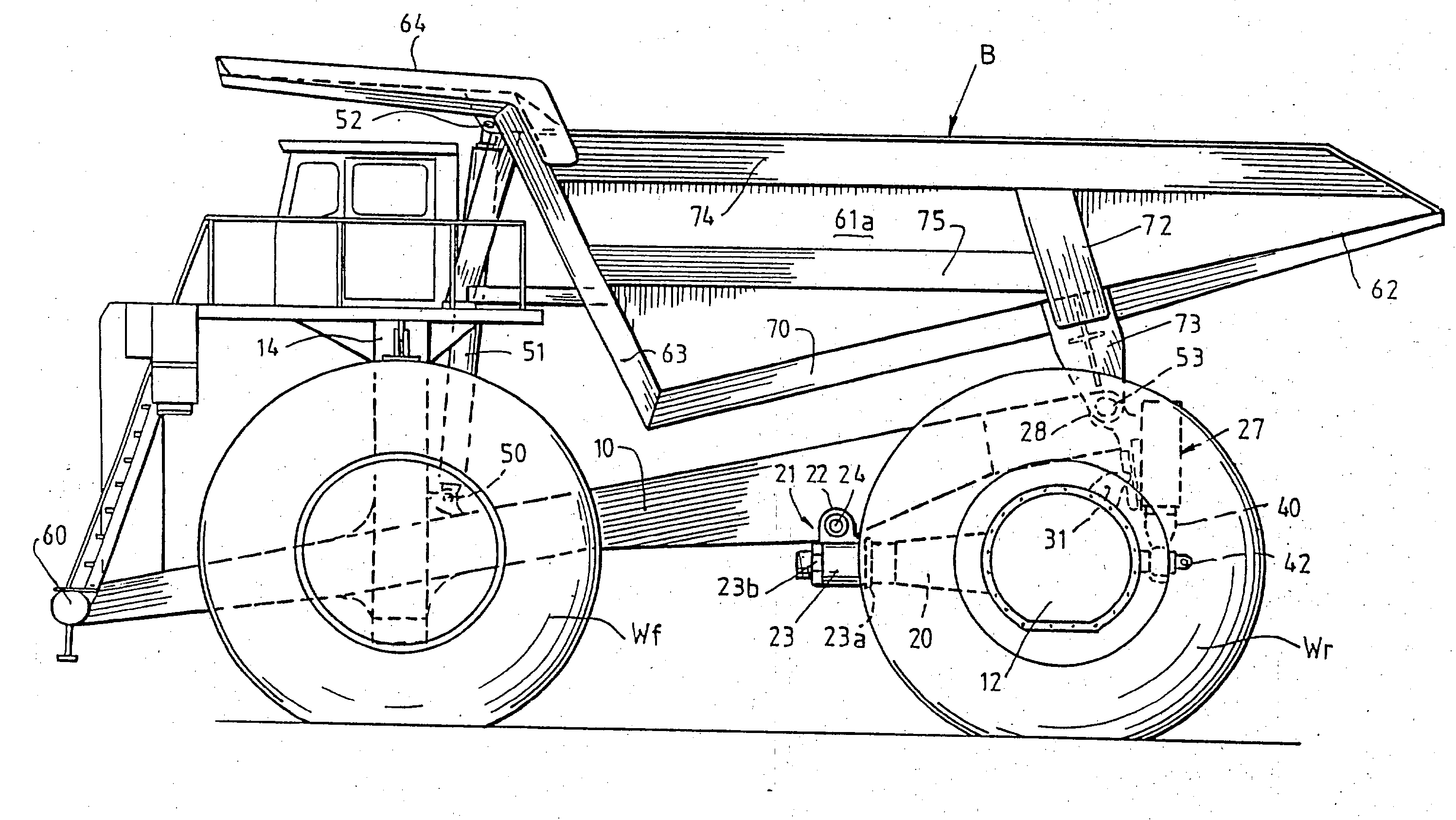
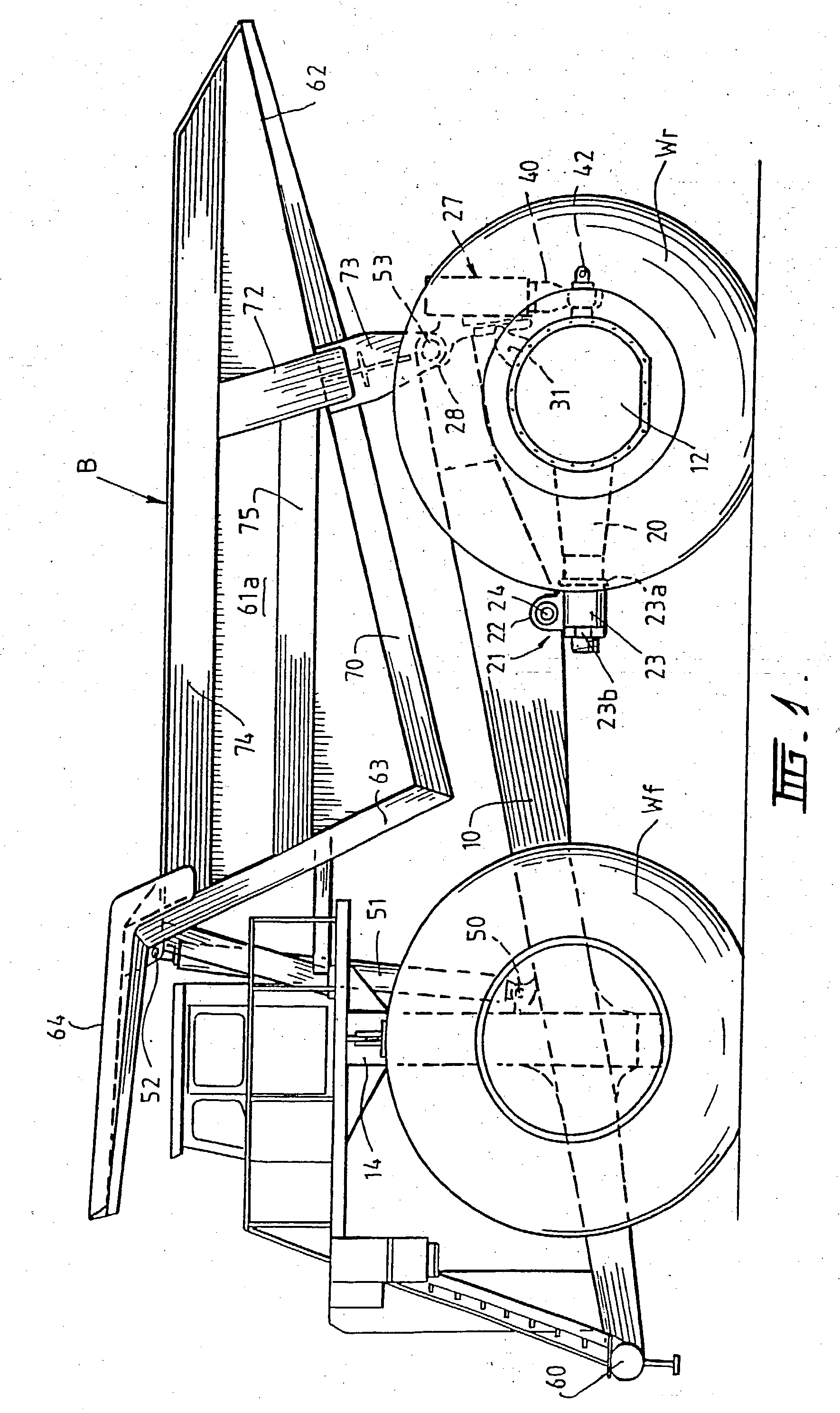
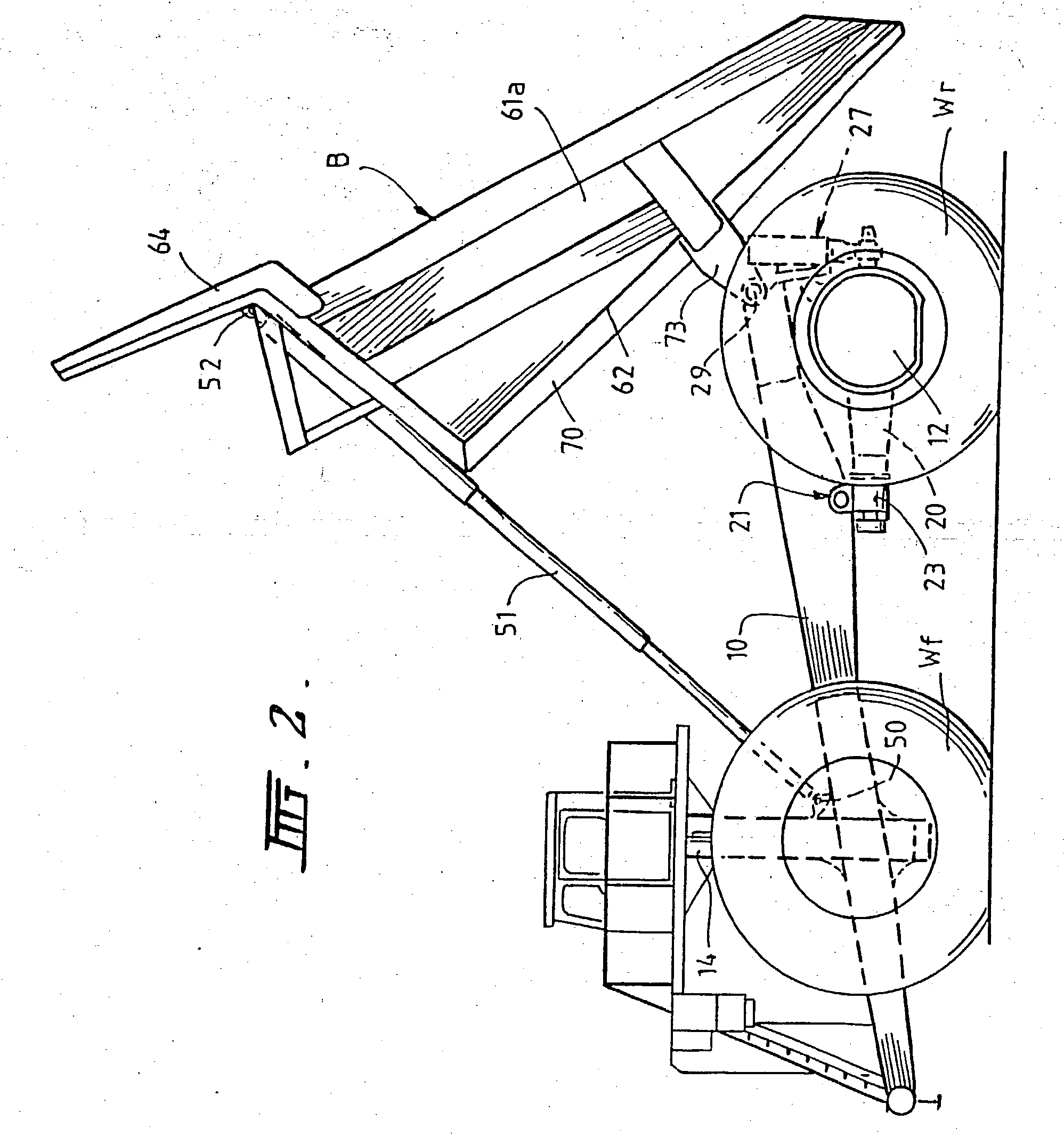
[0038] Referring to FIGS. 1 to 5 of the drawings, the truck frame comprises a pair of relatively light longitudinal members 10 and 11 suspending rear wheel mounting hubs 12 and 13 towards their rear ends. The longitudinal members 10 and 11 are connected at their forward ends by a substantial cross member 14, such as a mounting collar which generally includes mounting points for the front suspension (not shown) for the front wheels W.sub.f, at the front by a bumper 60 and at the rear, forwarding of the rear wheels, by a cross member 61, which forms part of the support means for the rear wheel mounting hubs 12 and 13, as will be described further below. The front suspension may take the form described in greater detail in our co-pending International Patent Application No. PCT / AU90 / 00084, or in any other suitable form.

[0039] As shown in FIGS. 3, 4 and 5, the wheel mounting hubs 12 and 13 support drive means for the rear wheels W.sub.r, such as electric traction motors 16, 17, 18 and 1...


PUM


Abstract

A suspension system for the main frame of a large dump truck having laterally spaced frame members (10) each associated with a wheel mounting hub (12) the system comprising, for each hub (12), a hollow forward attachment arm (20) supported by a bearing block (21) having a longitudinal journal (23) and a transverse journal (22), the longitudinal journal (23) receiving the attachment arm (20) and the transverse journal (22) receiving the ends of a shaft rigidly secured to the frame members (10) and extending therebetween to define a cross member and a vertically compliant suspension strut comprising a cylinder (41) rigidly attached to a support (28) secured to the frame member (10) and receiving a piston (40) attached to a rear extension (42) from the hub (12) via a bearing which allows each hub (12) to rotate about longitudinal and transverse axes relative to the respective frame member (10). Also disclosed is dump truck body (B) having side walls (61), a floor (62) and an end wall (63), the floor (62) being reinforced by longitudinal reinforcing beams and by only one transverse beam (72). The side walls (61) slope inwardly, the floor (62) slopes downwardly and forwardly and the width of the floor (62) increases towards the rear of the body (B).

Description

[0001] This invention relates to, suspension systems and configurations for the main structural components of very large trucks of the type used in mining operations.[0002] There is much commonality between currently available large mining trucks made by different manufacturers and the following observations are generally applicable regardless of the truck manufacturer:[0003] The empty vehicle weight is a high proportion of the maximum gross vehicle weight. Typically the ratio of payload to empty vehicle weight is only about 1.4:1. This means that much of the cost of operating such trucks is related to moving the empty vehicle weight rather than the payload.[0004] The total width of the four rear tyres is large compared to the total width of the truck. Typically 65% of the total width of a truck is taken up by the four rear tyres. With present designs of truck this leads to a very narrow main frame for the truck and very high bending loads on the rear axle and rear wheel support sys...

Claims


Application Information

Patent Timeline
Patent Type & Authority Applications(United States)
IPC IPC(8): B60K7/00B60K17/04
CPCB60G2204/143B60G2204/416B60G2300/026B60K2007/0092B60K17/046B60K2007/0046B60K7/0007
Inventor MOLLHAGEN, KLAUS-PETER
Owner LIEBHERR WERK BIBERACH
Why Eureka
Try Eureka