Optical recording medium and method for recording data in the same

a technology of optical recording medium and data, applied in the direction of optical recording/reproducing/erasing method, recording strategy, instruments, etc., can solve the problems of difficult to improve long-time storage reliability, difficult to reproduce a signal having a good c/n ratio, and difficult to control the thickness of the first recording layer 31 and the second recording layer 32

Inactive Publication Date: 2004-02-26
TDK CORPARATION
View PDF75 Cites 36 Cited by
  • Summary
  • Abstract
  • Description
  • Claims
  • Application Information

AI Technical Summary

Problems solved by technology

However, since an organic dye is degraded when exposed to sunlight or the like, it is difficult to improve long-time storage reliability in the case where an organic dye is used as the material of the recording layer.
However, since the difference between the optical property of the record mark consisting of the eutectic formed of the elements contained in the two recording layers and those of other regions is not so large, it is difficult to record data in the optical recording medium only by forming a record mark of eutectic of elements contained in the two recording layers so that a reproduced signal having a good C/N ratio can be obtained.
In particular, in a next-generation type optical recording medium that offers improved recording density and has an extremely high data transfer rate, since the diameter of the laser beam spot used to record and reproduce data is required to be reduc...

Method used


Image

  • Optical recording medium and method for recording data in the same
  • Optical recording medium and method for recording data in the same
  • Optical recording medium and method for recording data in the same

Examples


working example 1

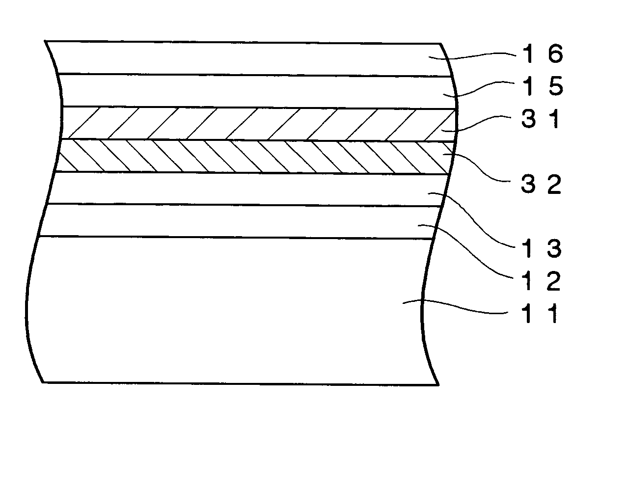
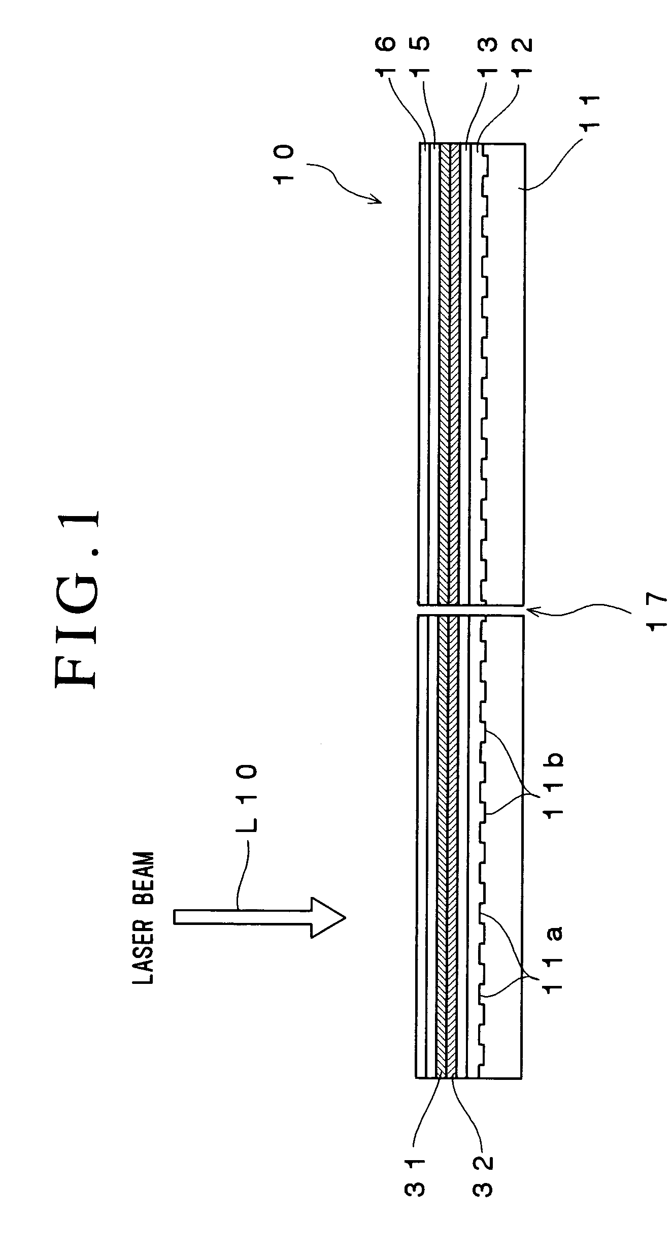
[0134] An optical recording medium sample #1 having the same structure as that shown in FIG. 1 was fabricated in the following manner.

[0135] A polycarbonate substrate having a thickness of 1.1 mm and a diameter of 120 mm was first set on a sputtering apparatus. Then, a reflective layer containing Ag as a primary component and having a thickness of 100 nm, a second dielectric layer containing a mixture of ZnS and SiO.sub.2 and having a thickness of 28 nm, a second recording layer containing Cu as a primary component, added with 21 atomic % of Mg and having a thickness of 5 nm, a first recording layer containing Si as a primary component and having a thickness of 5 nm and a first dielectric layer containing the mixture of ZnS and SiO.sub.2 and having a thickness of 22 nm were sequentially formed on the polycarbonate substrate using the sputtering process.

[0136] The mole ratio of ZnS to SiO.sub.2 in the mixture of ZnS and SiO.sub.2 contained in the first dielectric layer and the second...

working example 2

[0154] An optical recording medium sample #3 was fabricated in the manner of the optical recording medium sample #1, except that a second recording layer containing Al as the primary component and added with 17 atomic % of Mg was formed.

[0155] Similarly to the Working Example 1, data were recorded in the optical recording medium sample #3, and the first recording layer, the second recording layer, the first dielectric layer and the second dielectric layer in the optical recording medium sample #3 were observed.

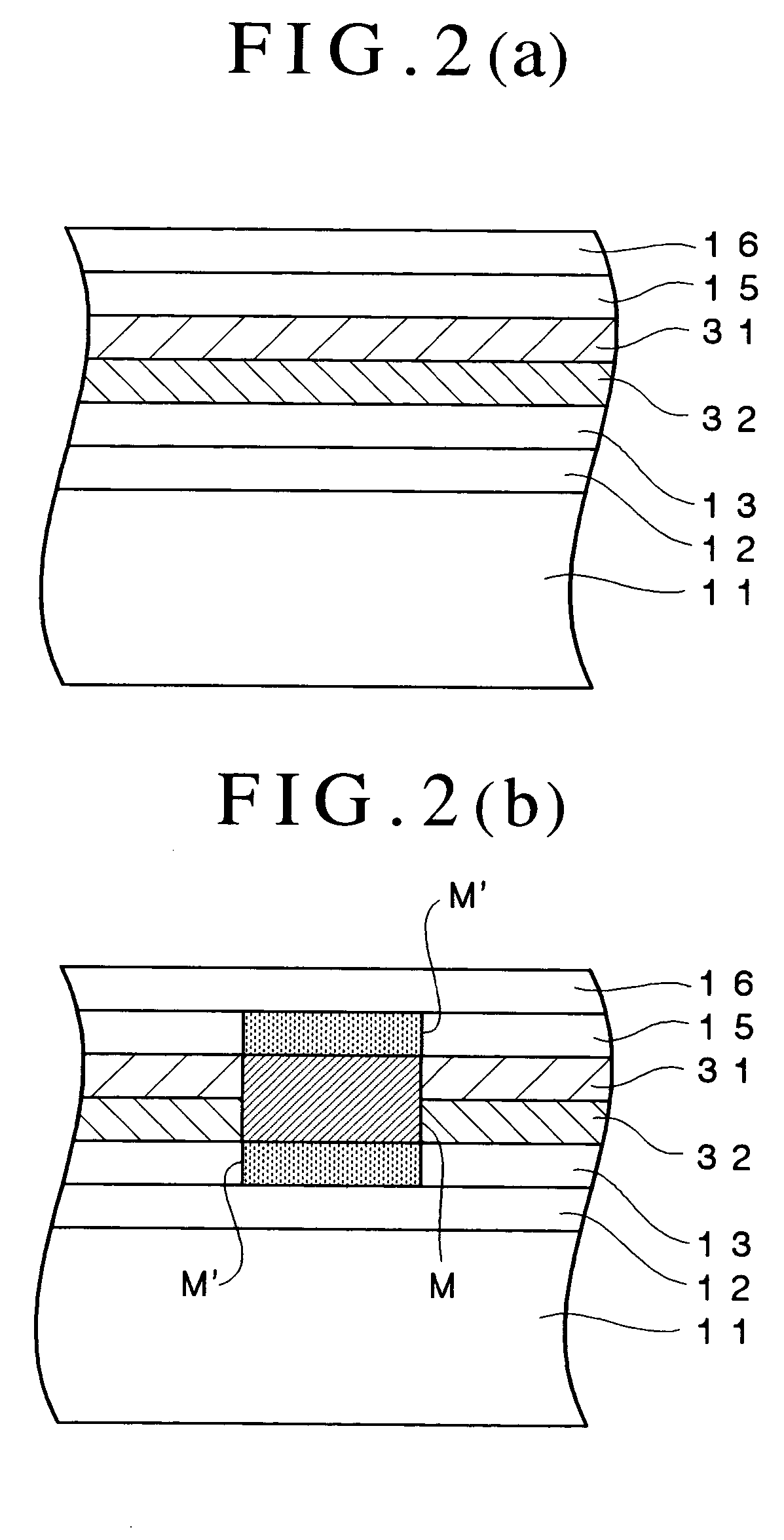
[0156] It was observed in the optical recording medium sample #3 that materials of the first recording layer and the second recording layer were mixed at a region where the record mark was formed and that materials of the first recording layer and the second recording layer were not mixed in the blank region.

[0157] Further, ZnS crystal was observed at regions of the first dielectric layer and the second dielectric layer adjacent to the record mark in the optical recording medi...

working example 3

[0159] An optical recording medium sample #4 was fabricated in the manner of the optical recording medium sample #1, except that a second recording layer containing Cu as the primary component and added with 23 atomic % of Al and 12.8 atomic % of Au was formed.

[0160] Data were recorded in the optical recording medium sample #4 using the optical recording medium evaluation apparatus used in the Working Example 1 and using a laser beam whose power was modulated in accordance with the single pulse pattern shown in FIG. 3.

[0161] The ground power Pb1 of the single pulse pattern was set to 0.1 mW and the recording power Pw1 thereof was set to 3.8 mW.

[0162] The other recording conditions were the same as those used in the Working Example 1.

[0163] Similarly, data were recorded in the optical recording medium sample #4 by modulating the power of the laser beam in accordance with the basic pulse train pattern shown in FIG. 4.

[0164] The width of each pulse of the basic pulse train pattern was ...


PUM


Abstract

An optical recording medium includes a substrate, two recording layers provided on the substrate and two dielectric layers each provided adjacent to one of the recording layers, the optical recording medium being constituted so that when it is irradiated with a laser beam having a wavelength lambda via an objective lens having a numerical aperture NA satisfying lambda/NA<=640 nm from the side opposite from the substrate, a record mark whose reflection coefficient is different from those of other regions of the recording layers is formed in the recording layers and at least a part of a region(s) of the dielectric layers adjacent to the record mark is crystallized to form a crystallized region. According to the thus constituted optical recording medium, it is possible to reproduce a signal having excellent signal characteristics.

Description

[0001] The present invention relates to an optical recording medium and a method for recording data in the optical recording medium and, particularly, to an optical recording medium capable of reproducing a signal having excellent signal characteristics and a method for recording data in the same so that a signal having excellent signal characteristics can be reproduced.DESCRIPTION OF THE PRIOR ART[0002] Optical recording media such as the CD, DVD and the like have been widely used as recording media for recording digital data. These optical recording media can be roughly classified into optical recording media such as the CD-ROM and the DVD-ROM that do not enable writing and rewriting of data (ROM type optical recording media), optical recording media such as the CD-R and DVD-R that enable writing but not rewriting of data (write-once type optical recording media), and optical recording media such as the CD-RW and DVD-RW that enable rewriting of data (data rewritable type optical r...

Claims


Application Information

Patent Timeline
IPC IPC(8): G11B5/66G11B7/0045G11B7/24067G11B7/243G11B7/257
CPCG11B7/00455G11B7/00456G11B7/257G11B7/243G11B7/24067
Inventor INOUE, HIROYASUMISHIMA, KOJIAOSHIMA, MASAKI
Owner TDK CORPARATION
Why Eureka
Try Eureka