X-Y stage system with onboard linear motor

Active Publication Date: 2004-03-18
NIPPON THOMPSON
View PDF14 Cites 14 Cited by
  • Summary
  • Abstract
  • Description
  • Claims
  • Application Information

AI Technical Summary

Problems solved by technology

Thus, it remains a major challenge to provide a slider unit with onboard moving-magnet linear motor, which advances in conduction system for armature windings, selection of material for field magnet, selection of encoder high in resolving-power and fixture construction of sensor cords to make the slider unit nimble in operation, les

Method used


Image

  • X-Y stage system with onboard linear motor
  • X-Y stage system with onboard linear motor
  • X-Y stage system with onboard linear motor

Examples


Embodiment Construction

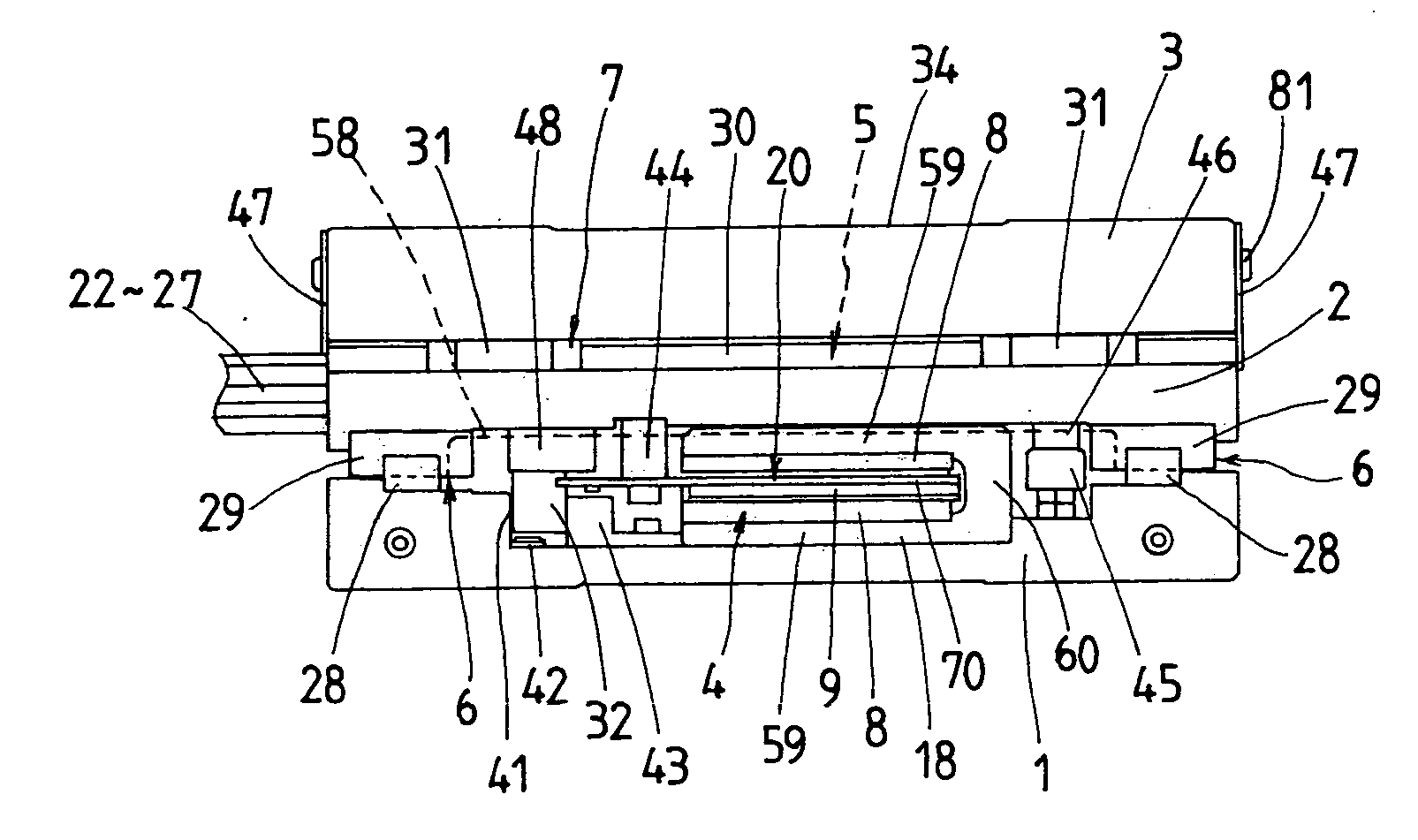
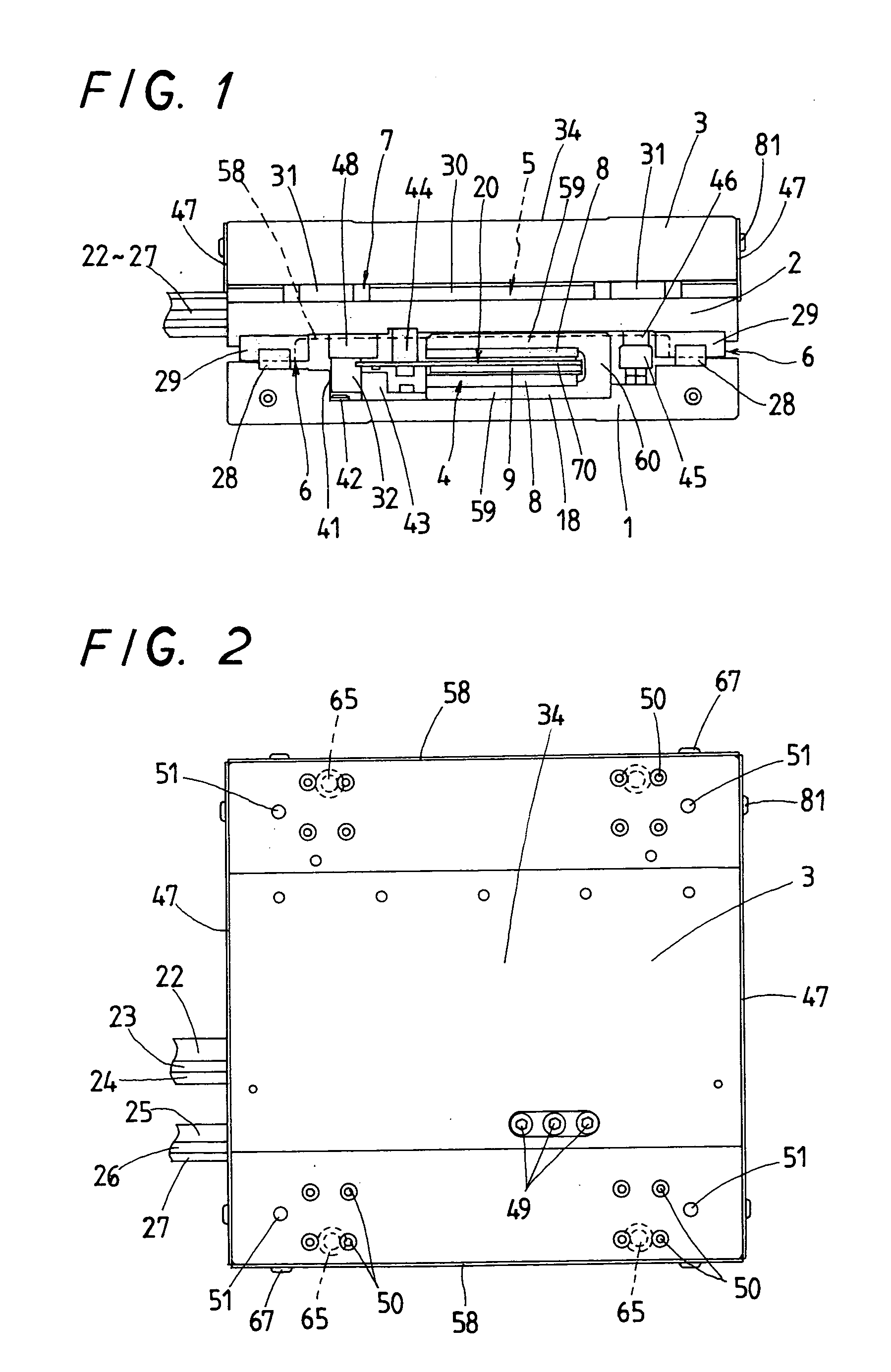
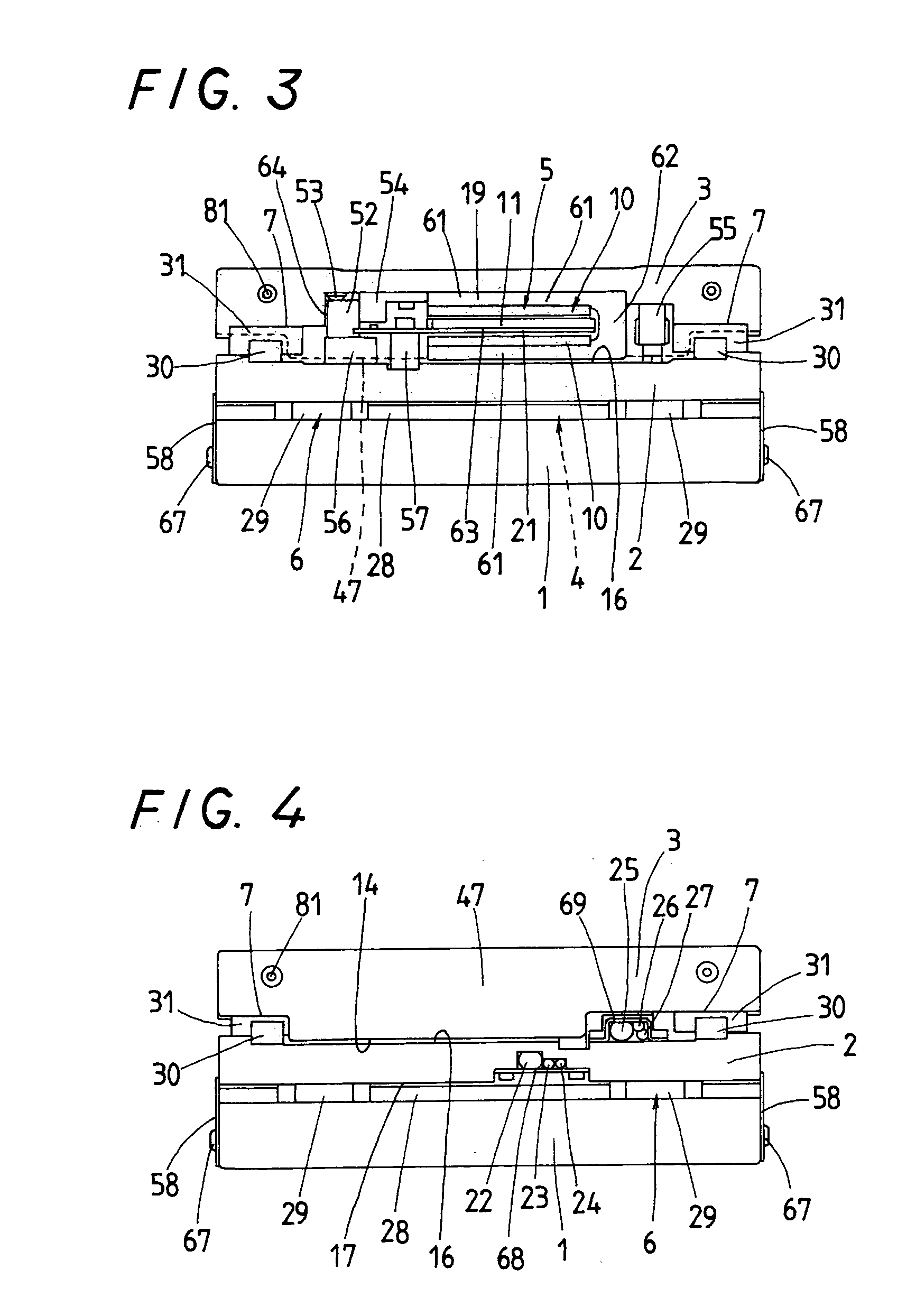
[0045] Preferred embodiments of an X-Y stage system according to the present invention will be explained hereinafter in detail with reference to the accompanying drawings. The X-Y stage system of the present invention is designed to serve well for machinery including semiconductor and liquid display manufacturing equipment, measuring instruments, assembling machines, tool machines, industrial robots, conveyors, and generally provided therein with onboard first and second linear motors. The first linear motor 4 is built in between an X-stage 2 and a stationary bed 1 and made up of first armature windings 9 lying below a lower surface 17 of the X-stage 2 and first field magnets 8 disposed on the stationary bed 1 in opposition to the first armature windings 9. The second linear motor 5 is built in between the X-stage 2 and a Y-stage 3 and made up of second armature windings 11 lying above an upper surface 16 of the X-stage 2 and second field magnets 10 disposed underneath the Y-stage 3...


PUM


Abstract

An X-Y stage system is disclosed which is easy to assemble and compact or slim in construction. Both the X- and Y-stages are allowed to move without getting influence from the magnetic force created by the field magnets. The X-Y stage system has an X-stage movable relatively to a bed through a linear motion guide unit in an X-direction, and a Y-stage movable relatively to the X-stage through another linear motion guide unit in a Y-direction. The linear motors to force the X- and Y-stages are composed of paired field magnets of secondary side held to the bed and the Y-stage, respectively, and armature windings of primary side supported on the opposite sides of the X-stage in a way lying in clearances between the opposing field magnets.

Description

[0001] 1. Field of the Invention[0002] The present invention relates to an X-Y stage system with onboard linear motor, which has been extensively used in machinery including semiconductor and liquid display manufacturing equipment, measuring instruments, assembling machines, tool machines, industrial robots, conveyors and, more particularly, to an X-Y stage system with onboard linear motor in which an armature winding of primary side is installed on, for example, a turntable while a field magnet of secondary side lies on a stationary bed.[0003] 2. Description of the Prior Art[0004] In recent years, current multi-axis stage systems and moving mechanisms such as X-Y plotters employed in the diverse technical fields using machinery as stated earlier have required more and more a position-control stage, which is made compact or slim in construction and light in weight, and moreover able to operate with high propulsion, high speed and high response to allow a moving object including work...

Claims


Application Information

Patent Timeline
IPC IPC(8): B23Q1/62B23Q5/28H02K41/03
CPCB23Q1/621H02K41/03B23Q5/28
Inventor TSUBOI, TAKAAKIIDA, EIJI
Owner NIPPON THOMPSON
Why Eureka
Try Eureka