

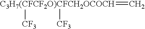
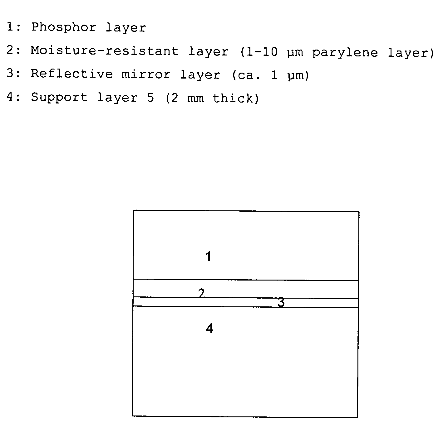
Binderless storage phosphor screen
a phosphor screen and binding technology, applied in the field of binding storage phosphor screens, can solve the problems of loss of spatial resolution and contrast in images, limited quantum efficiency, and not all psl centres are stimulated in the read-out process, and achieve the effects of reducing resolution, high sensitivity, and efficient creation and detection
- Summary
- Abstract
- Description
- Claims
- Application Information
AI Technical Summary
Benefits of technology
Problems solved by technology
Method used
Image

Examples
Embodiment Construction
[0123] A. Preparation of the Vapour Deposited Screens:
[0124] CsBr:Eu screens were made via thermal vapour deposition of CsBr and EuOBr. To this aim, CsBr was mixed with EuOBr and was placed in a container in a vacuum deposition chamber. The phosphor was deposited on a substrate. During vapour deposition, the substrate was rotated.
[0125] Different screens were produced with differing substrates. Before the start of the evaporation, the chamber was evacuated to a pressure of 4.10.sup.-5 mbar.
[0126] A first screen (S-D) was made with an Al substrate. Because of its composition and surface roughness the Al substrate was dull and did not reflect in a mirrorlike way.
[0127] A second screen was made on an a-C substrate on which an Al mirror was applied by vapour deposition (S-M). The substrate had a clear mirrorlike reflection, because of the surface smoothness and because of the pureness of the aluminum.
[0128] For both screens the deposited CsBr:Eu layer had a thickness of about 160 .mu.m....
PUM
| Property | Measurement | Unit |
|---|---|---|
| reflectivity | aaaaa | aaaaa |
| surface roughness | aaaaa | aaaaa |
| reflectivity | aaaaa | aaaaa |
Abstract
Description
Claims
Application Information