Sublimation pattern casting method

Inactive Publication Date: 2004-04-01
KAO CORP
View PDF2 Cites 7 Cited by
  • Summary
  • Abstract
  • Description
  • Claims
  • Application Information

AI Technical Summary

Benefits of technology

1 TABLE 1 first second first degree of second pressure pressure ventilation (flow degree of loss loss rate of gas based ventilation (Note 5 Casting (calculated (actual on extrapolation (airflow Overall time value) value) from a calibration rate evalua- (second) (g / cm.sup.2) (g / cm.sup.2) curve) 2L / min.) observed Casting quality of cast product tion Example 1 10 6 29 95 7937 A blow-back phenomenon and carbon residue defects were .circleincircle. the like did not occur, enabling observed neither on the smooth casting sides nor on the upper mold surface 2 14 58 98 5.6 338 A blow-back phenomenon and A few carbon residue defects .largecircle..about..DELTA. the like did not occur, enabling were observed on both sides smooth casting and upper mold surface 3 7 0.8 19 800 48100 A blow-back phenomenon and A few carbon residue .largecircle. the like did not occur, enabling defects were observed on smooth casting the upper mold surface 4 30 13 330 15 256 A blow-back phenomenon and carbon residue defects were .DELTA. the like did not occur, enabling observed on the sides and smooth casting the upper mold surface 5 9 6 28 (Note 1) (Note 1) A blow-back phenomenon and carbon residue defects were .DELTA. the like did not occur,but flame observed on the sides and spurted from the end of the the upper mold surface capillary Compar- ative example 1 53 (Note 2) (Note 2) (Note 3) (Note 3) The molten metal was Many carbon residue X blown back violently in the defects were observed on initial stage of casting the sides and the upper mold surface 2 6 0.01 Less (Note 1) (Note 1) A brow-back phenpmenon did A few carbon residue X than not occur,but the molten metal defects were observed 0.5 was spurted violently from the the upper mold surface exhaust hole 3 41 (Note 4) 8 (Note 4) 7937 The molten metal was blown Many carbon residue defects X back violently from the gate in were observed on the sides the initial stage of casting the upper mold surface

Problems solved by technology

It has however, on the contrary, the drawbacks that casting defects are easily caused by defective degassing control, the strength of the model is low and therefore it is easily deformed and damaged so that sand cannot be filled strongly, leading to unsatisfactory packing density, resulting in insufficient pattern strength and causing burning fusion.
However, in such a method intending to obtain casting products with small defects by efficiently exhausting the gas generated from an evaporative pattern to the outside as disclosed in each publication of JP-A Nos. 5-261470, 8-206777 and 11-90583, the distribution of pressure of the gas layer created in the pattern becomes so large that the molten metal is blown up along the gas passage because the exhaust speed of the combustion gas is too high.
As a result, there is the case where the molten metal is largely disturbed in the pattern so that the carbon residue and the generated gas are involved in the molten metal, which promotes the generation of defects.
Conventionally, if a coating material containing refractory aggregates having a fine particle diameter is used for evaporative pattern casting process, the permeability of a coating film is dropped and increases in carbon residue defects and gas defects are seen.

Method used


Image

  • Sublimation pattern casting method
  • Sublimation pattern casting method
  • Sublimation pattern casting method

Examples


example 1

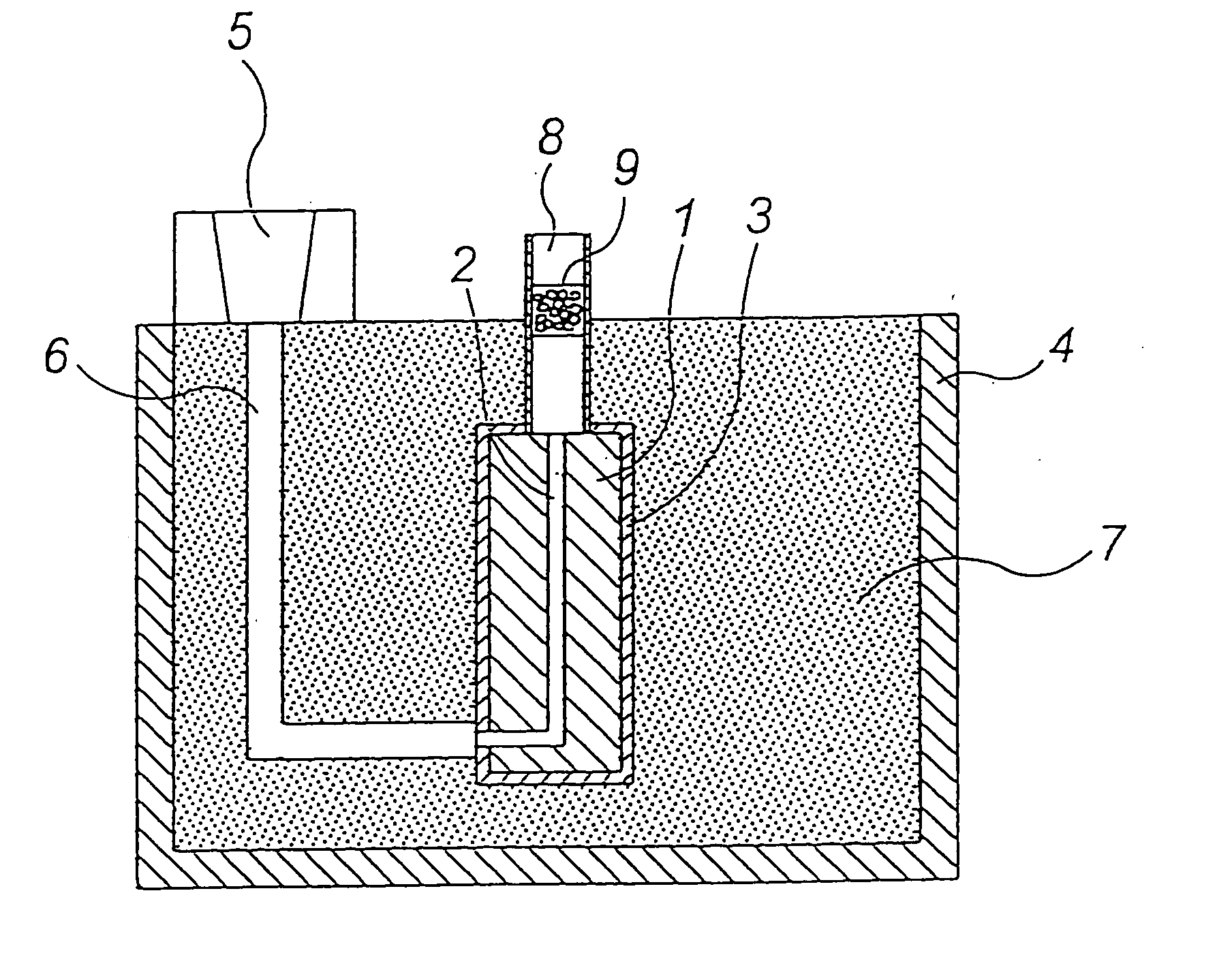
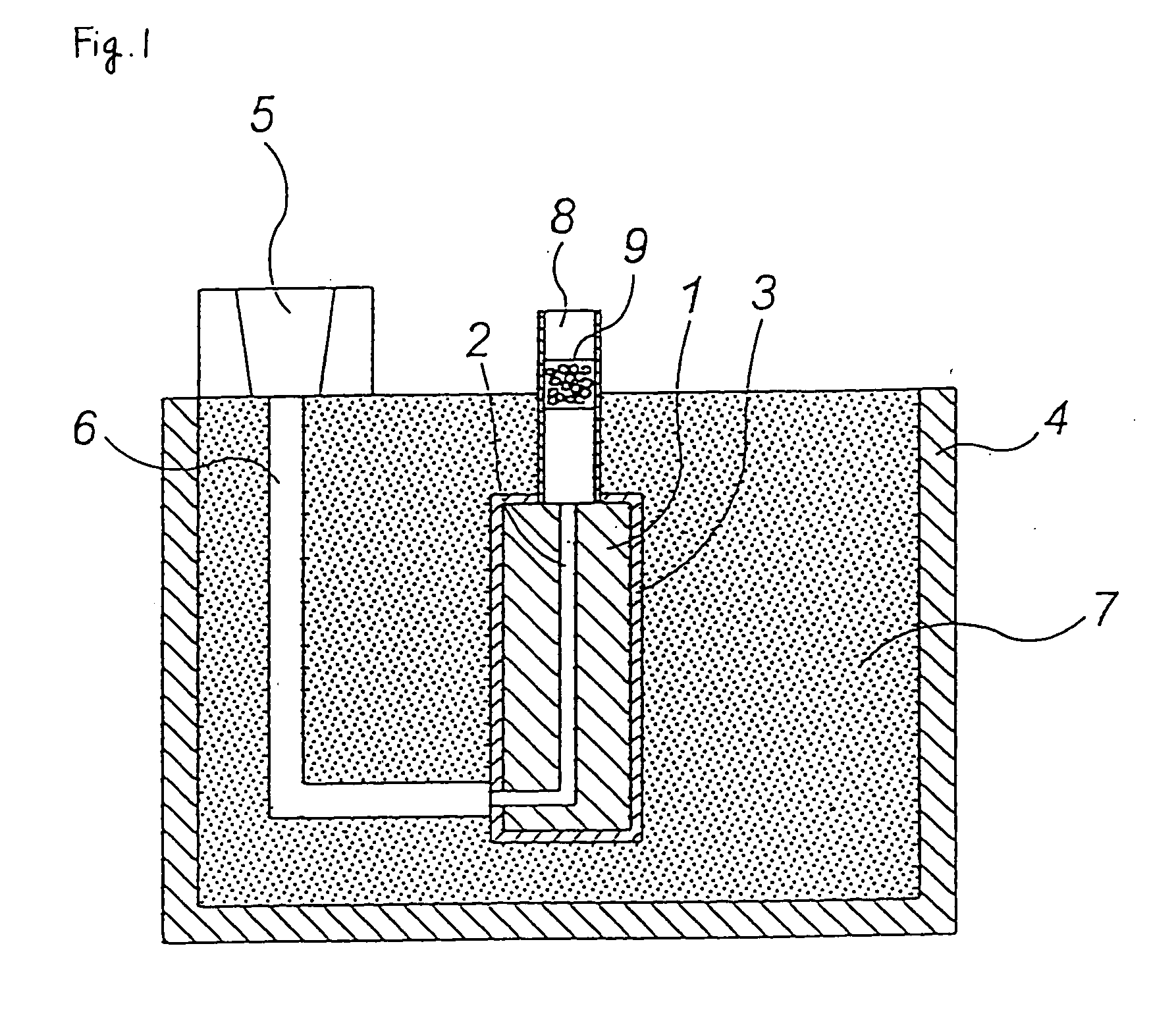
[0032] A through-hole 2 was formed in a 120 mm.times.80 mm.times.250 mm-H foamed pattern 1 (made of an expanded polystyrene) by using a heated metal bar having a diameter of 3 mm as shown in FIG. 1. The diameter of the through-hole was about 4 mm.

[0033] A 2-mm-diameter spherical alumina 9 mixed with an ester-curable phenol resin was filled in a 4-cm-diameter cylindrical ceramic tube (length: 30 cm) such that the thickness (h) of alumina 9 in layer was 2.5 cm and cured, to form an exhausting path 8.

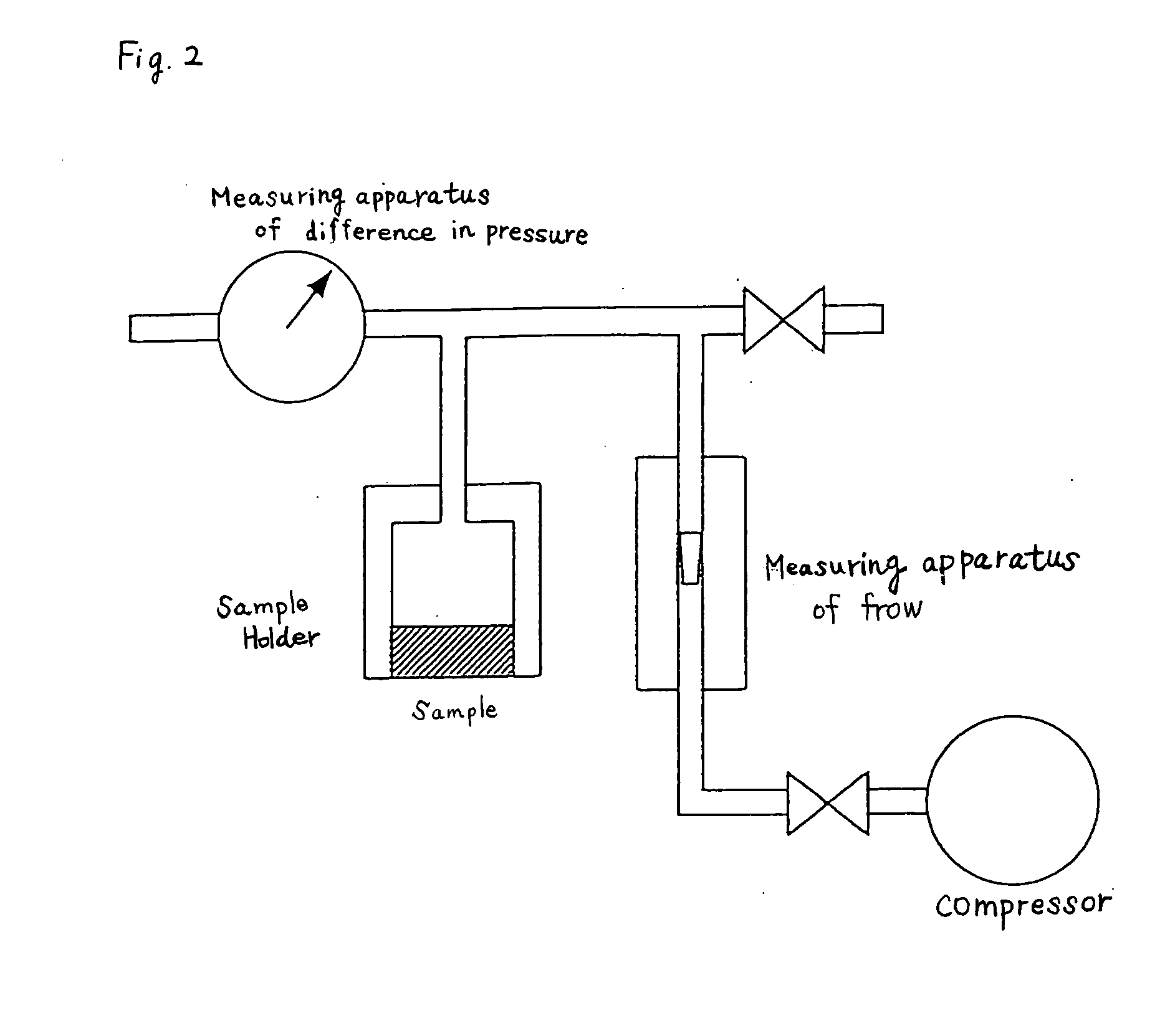
[0034] With regard to this exhausting path 8, pressure loss P was measured as shown in FIG. 2. As a result, P=0.02 g / cm.sup.2 when air ventilation rate was 1 L / min., P=0.08 g / cm.sup.2 when air ventilation rate was 3 L / min. and P=0.15 g / cm.sup.2 when air ventilation rate was 5 L / min. In this example, pouring time (t) was set to 10 seconds and therefore the quantity of gas to be exhausted was about 172 L / min. The first pressure loss was 6 g / cm.sup.2 when the quantity of gas was 172 L / min.

[00...

examples 2 to 4

[0041] A casting operation was carried out in the same manner as in Example 1 except that the pouring time, the pressure loss and the degree of ventilation in the exhaust gas-controlling means were changed as shown in Table 1 and the same evaluation as in Example 1 was made. The results are shown in Table 1.

[0042] In Example 2, spherical alumina 0.5 mm in diameter was filled such that the thickness of the alumina layer was 2 cm. The pressure loss P in the exhausting path was as follows: P=0.47 g / cm when air ventilation rate was 1 L / min., P=1.41 g / cm.sup.2 g / cm when air ventilation rate was 3 L / min. and P=2.36 g / cm.sup.2 when air ventilation rate was 5 L / min.

[0043] Also, in Example 3, spherical alumina 5 mm in diameter was filled such that the thickness of the alumina layer was 2 cm. The pressure loss P in the exhausting path was as follows: P=0.0033 g / cm when air ventilation rate was 1 L / min., P=0.0099 g / cm.sup.2 when air ventilation rate was 3 L / min. and P=0.0165 g / cm.sup.2 when ai...

example 5

[0045] A casting operation was carried out in the same manner as in Example 1 except that a stainless fine tube having an inside diameter of 8.8 mm and a length of 600 mm was used as the exhaust gas-controlling means and no exhausting path was not installed (the fine tube is used as the exhausting path, too), and the same evaluation as in Example 1 was made. The fine tube was disposed in such a manner as to be communicated with the through-hole of the model. The pressure loss P in the exhausting path was as follows: P=0.02 g / cm.sup.2 when air ventilation rate was 1 L / min., P=0.09 g / cm.sup.2 when air ventilation rate was 3 L / min. and P=0.16 g / cm.sup.2 when air ventilation rate was 5 L / min. The results are shown in Table 1.


PUM


Abstract

Provided is an evaporative pattern casting process which ensures that smooth casting can be carried out without blow-back of a molten metal and a molding product having an excellent casting quality is obtained. The invention relates to an evaporative pattern casting process for casting a product, which comprises pouring a molten metal into a mold provided with a pattern with a through-hole, embedded in molding sand, and evaporating the pattern with the poured molten metal, gradually exhausting the gas generated by the evaporation of the pattern to the outside of the mold through an exhausting path provided with an exhaust gas-controlling means.

Description

[0001] The present invention relates to an evaporative pattern casting process, in particular an evaporative pattern casting process for carrying out casting by exhausting gas generated from the evaporative pattern to the outside of the pattern through an exhausting path.PRIOR ART[0002] An evaporative pattern casting process which is also called a full mold casting process is a casting process in which generally an evaporative pattern made of an expandable polystyrene or the like is embedded in a molding sand, a molten metal is poured into the pattern to vaporize and to evaporate the evaporative pattern by the heat of the molten metal and also a molten metal is filled in the generated gap, thereby making a molded article. This process is widely used for manufacturing, particularly, a press die.[0003] The evaporative pattern casting process has many advantages such as the capability of casting into an exact form. It has however, on the contrary, the drawbacks that casting defects are...

Claims


Application Information

Patent Timeline
IPC IPC(8): B22C9/04
CPCB22C9/046
Inventor NAKAI, SHIGEOKAGITANI, MASAHIKOTAKAGI, YOSHIMASANURUSHIMA, TAKESHIFUNADA, HITOSHI
Owner KAO CORP
Why Eureka
Try Eureka