Composite high temperature insulator

a high-temperature insulation and composite technology, applied in the field of composite materials, can solve the problems of low strength of materials, hot spots can occur, and slow dissipation of conductive heat in the plane of sheets,

Inactive Publication Date: 2004-04-22
UCAR CARBON TECH
View PDF2 Cites 49 Cited by
  • Summary
  • Abstract
  • Description
  • Claims
  • Application Information

AI Technical Summary

Problems solved by technology

However, hot spots can occur since dissipation of conductive heat in the plane of the sheet is relatively slow.
Such materials tend to

Method used


Image

  • Composite high temperature insulator
  • Composite high temperature insulator
  • Composite high temperature insulator

Examples


Embodiment Construction

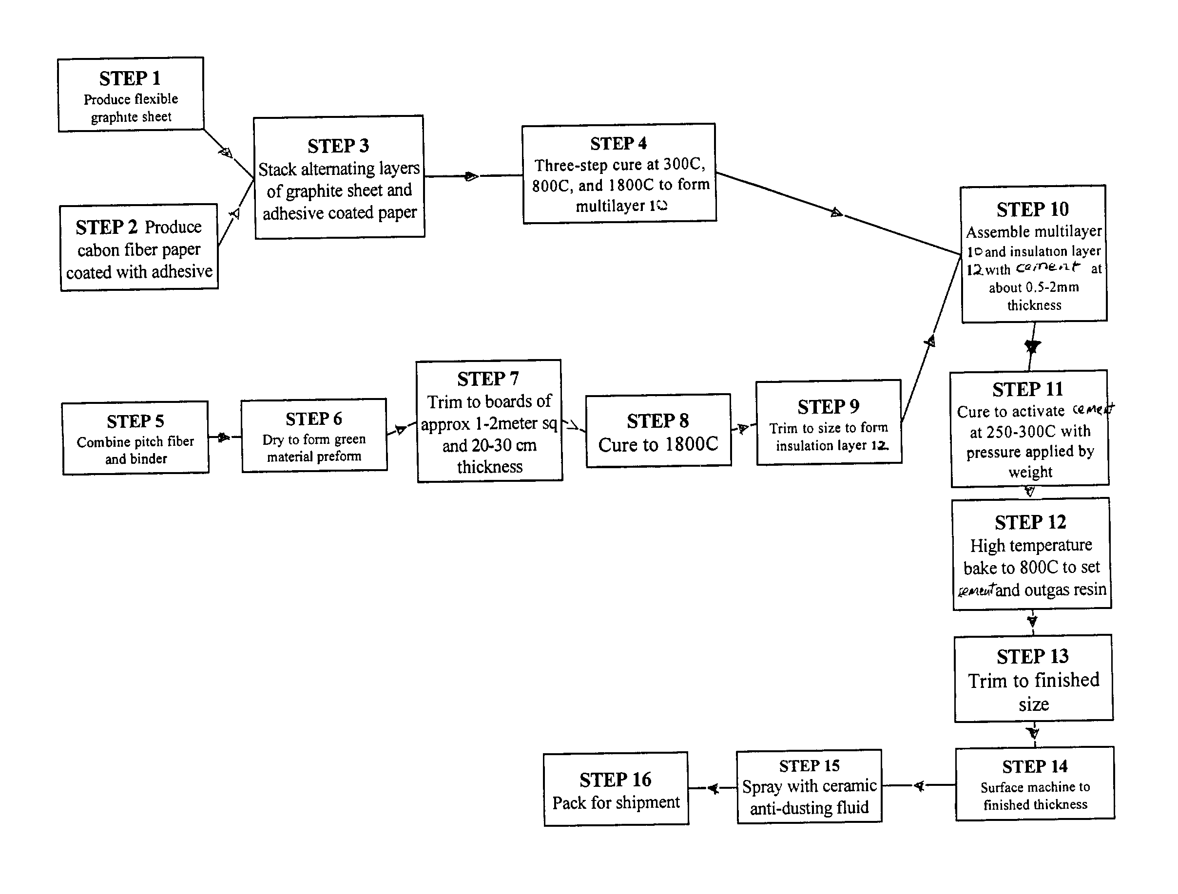
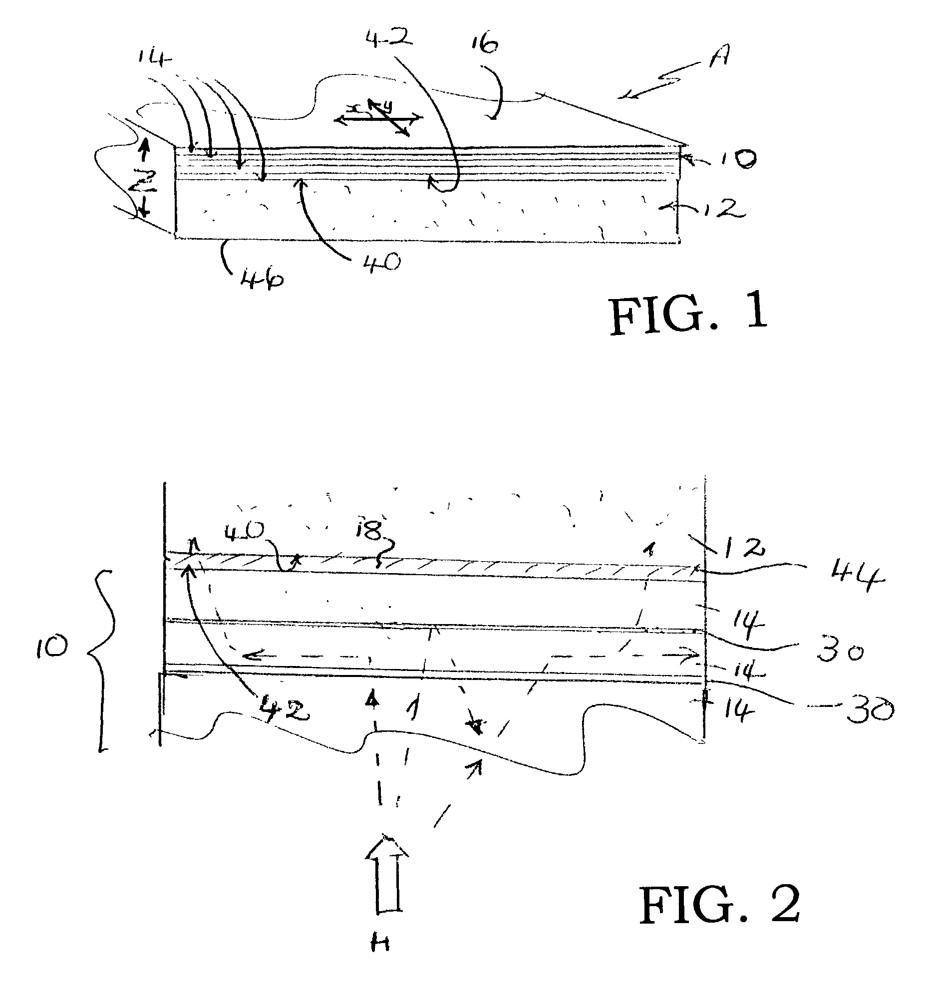
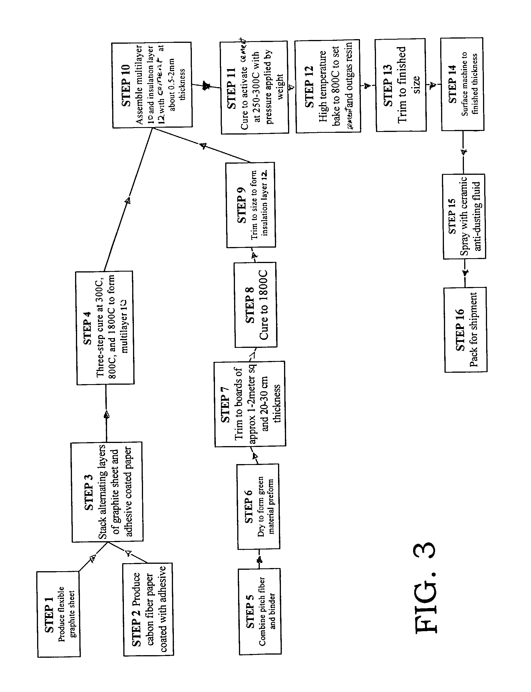
[0077] A layer 10 about 0.535 cm thick was formed from about 6 layers 14 of GRAFOIL.RTM. sheets sandwiched together with alternating layers of kraft paper 20 coated on both sides with a phenolic resin 22, 24. The layered assembly was subjected to a three step cure at 300.degree. C., 800.degree. C., and 1800.degree. C. to form layer 10. The thermal conductivity of layer 10 was 3W / m.multidot.K in the z direction and 140 W / m.multidot.K in the plane of the layer (x and y directions).

[0078] Rigid insulation material for layer 12 was formed from pitch fibers and a binder, which was cured to a final temperature of 1800.degree. C. in a non-oxidizing atmosphere. The rigid insulation material had a thickness of 1.605 cm and a thermal conductivity of 0.2 W / m.multidot.K in the z direction and 0.2 W / m.multidot.K in the plane of the layer (x and y directions).

[0079] Layer 12 was attached to layer 10 with a cement paste composition comprising 20 to about 60 wt. % of a carbon filler, 7 to about 30 ...


PUM

PropertyMeasurementUnit
Linear densityaaaaaaaaaa
Thicknessaaaaaaaaaa
Thicknessaaaaaaaaaa

Abstract

A composite high temperature insulator (A) includes a planar layer (10) having anisotropic thermal conductivity properties. A second planar layer (12) is formed from a rigid insulation material, such as a carbonized mixture of carbon fibers and a binder. The second layer is coextensive with the first layer and is preferably bonded thereto by a carbonaceous cement (44). When used to insulate a heat source, such as a furnace (50), convective heat is directed back to the source by the reflective surface (16) of the inner, anisotropic layer (10). Heat which enters the anisotropic layer is dissipated evenly through the plane of the layer along a plurality of heat paths defined by a plurality of layers (14) of flexible graphite. Accordingly, heat which reaches the outer, second layer (12) results in fewer hot spots than occur with a conventional rigid insulation material, thereby reducing the total amount of insulation material required to achieve a desired level of thermal insulation.

Description

[0001] 1. Field of the Invention[0002] The present invention relates to a thermal insulation material suited to high temperature applications. In particular, it relates to a composite material comprising one or more layers of flexible graphite and one or more layers of an isotropic carbon insulator, and will be described with particular reference thereto.[0003] 2. Discussion of the Art[0004] Thermal insulation materials formed from carbon fibers exhibit excellent resistance to heat flow, even at high temperatures. Traditionally, a mixture of carbonized cotton or rayon fibers and a binder, such as a phenolic resin, furfuryl alcohol, or starch, is poured into a form or mold fitted with a filter, known as a bleeder cloth. A vacuum is pulled on the bleeder cloth to remove the excess binder. The fibers build up on the bleeder cloth and when the desired thickness is achieved, the fibers are removed as a mat. The mat is dried and carbonized, for example, by induction heating to a temperatu...

Claims


Application Information

Patent Timeline
IPC IPC(8): B32B9/00C04B26/10C04B26/12C04B26/26C04B26/28C04B37/00F16L59/02F27D1/00
CPCB32B9/00Y10T428/30B32B38/0036B32B2307/304B32B2309/022B32B2313/04C04B26/105C04B26/122C04B26/26C04B26/28C04B37/008C04B2111/00612C04B2111/28C04B2235/48C04B2235/77C04B2235/9607C04B2237/363C04B2237/385C04B2237/704F16L59/029F27D1/0006B32B18/00C04B2237/708C04B2237/086C04B2235/6567C04B2235/6562C04B35/63476C04B35/636C04B37/005C04B2235/5248C04B14/386C04B18/10C04B18/101C04B40/0268Y10T428/249928Y02W30/91C04B35/83C04B35/6261C04B2235/526C04B2235/5264C04B35/6309C04B2235/3284C04B2235/444C04B35/522C04B2235/602B32B9/007B32B2262/106B32B9/04B32B2309/105
Inventor BLAIN, DAVID P.SMITH, ROBERT E.
Owner UCAR CARBON TECH
Why Eureka
Try Eureka