Methods and apparatus for indicating a fault condition in fuel cells and fuel cell components

a technology of fuel cells and fault conditions, applied in the direction of fuel cells, fuel cell auxiliaries, instruments, etc., can solve the problems of limited conversion of all fuels, negative impact on cell performance, and limited practical systems

Inactive Publication Date: 2004-05-13
GREENLIGHT POWER TECH
View PDF30 Cites 53 Cited by
  • Summary
  • Abstract
  • Description
  • Claims
  • Application Information

AI Technical Summary

Problems solved by technology

However, practical systems are limited to a few fuel choices, such as hydrogen natural gas and methanol and usually use the oxygen present in air as the oxidant stream.
All these conversions are limited by the heat transfer properties of real structural materials within the fuel cell.
However, water present in other regions of the cell, such as gas diffusion layers or flow field channels, can have a negative impact on cell performance by hindering access of reactants to catalyst sites within the fuel cell.
Different combinations of these parameters can affect the performance of the fuel cell in similar ways and thus, it is difficult to discern their separate contributions or detrimental effects on performance.
This results in ohmic heating and imposes additional thermal stresses on dehydrated regions of the membrane.
These regions become depleted of water more rapidly with rising temperatures.
Under these conditions, usually known as brown-outs, regions of the polymer can burn and rupture.
The effects of this type of failure are that the ionic conductor is irreversibly damaged and the effectiveness of the membrane on reactant separation is compromised.
This is particularly catastrophic for serial, high current applications where the geometric power densities are high.
Failures of this type in one cell within a serial PEMFC stack will halt current production for the entire stack and more importantly could present a safety haz

Method used


Image

  • Methods and apparatus for indicating a fault condition in fuel cells and fuel cell components
  • Methods and apparatus for indicating a fault condition in fuel cells and fuel cell components
  • Methods and apparatus for indicating a fault condition in fuel cells and fuel cell components

Examples


Embodiment Construction

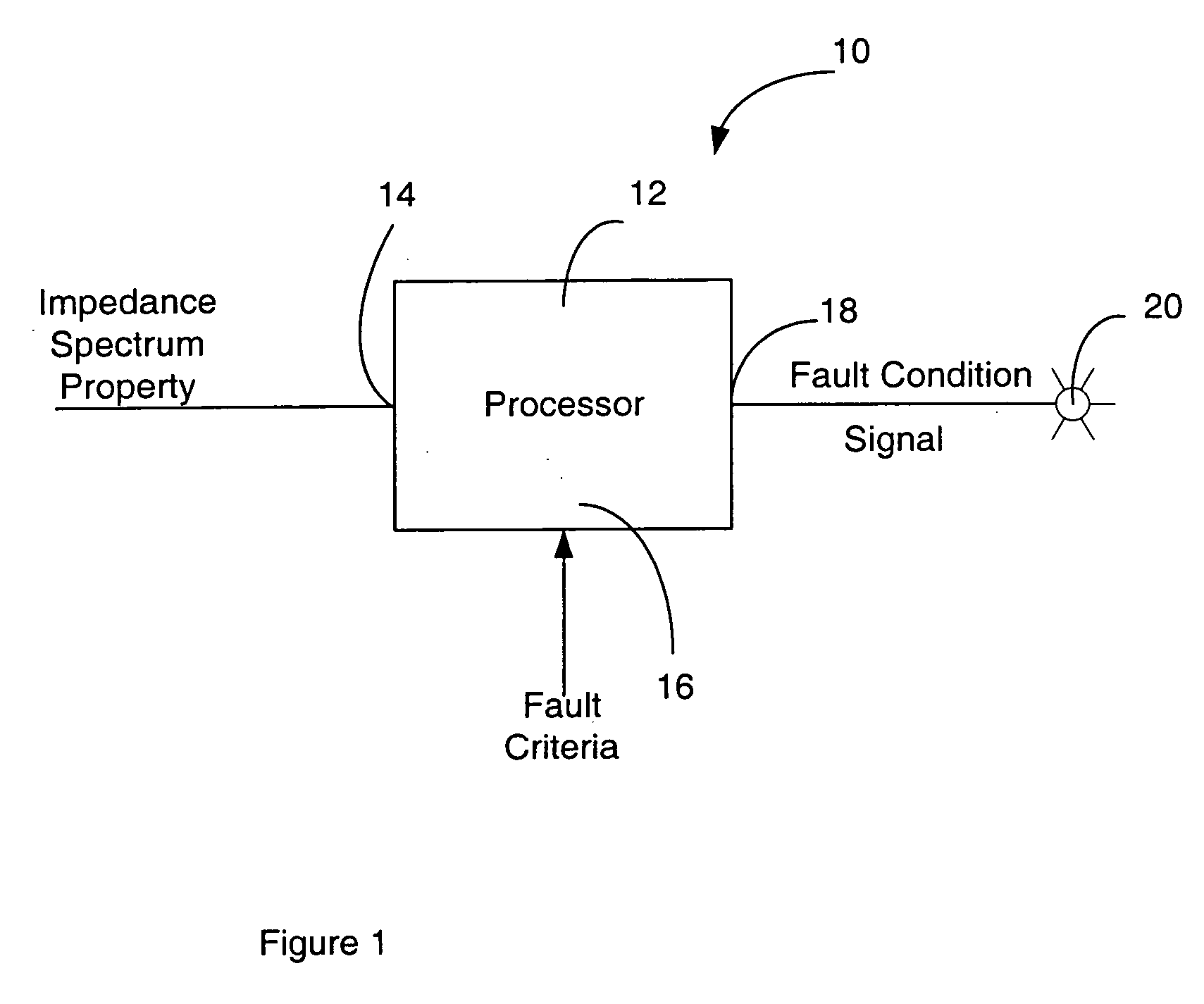
[0053] Referring to FIG. 1, an apparatus for indicating a fault signal in a fuel cell, according to a first embodiment of the invention, is shown generally at 10. In this embodiment the apparatus includes a processor 12 having an input 14 for receiving an impedance spectrum property and has a second input 16 for receiving fault criteria. The processor also has an output 18 at which it produces a fault condition signal indicating a specific fault condition when the property of the impedance spectrum received at the input 14 meets the criteria received at the input 16. The fault condition signal may be a simple on / off signal used to control an indicator lamp such as shown at 20, for example. In general, the fault condition signal may be used to control any type of annunciator for alerting an operator of a fault condition or may be used to initiate a process for alerting an operator.

[0054] By appropriate input of fault criteria and appropriate input of an impedance spectrum property, t...


PUM


Abstract

An apparatus and methods for detecting and identifying faults in a fuel cell are disclosed. An impedance spectrum relating to the fuel cell is compared with fault criteria to identify fault conditions in the fuel cell. A time-varying current is drawn from the fuel cell at a selected frequency and the impedance of the fuel cell at the frequency is measured. This may optionally be repeated at a range of frequencies or at combinations of frequencies to provide an impedance spectrum across the range of frequencies. The fault criteria identify one or more fault conditions that may be identified by comparing the measured impedance spectrum to the fault conditions.

Description

[0001] This invention relates to methods and apparatus for indicating fault conditions in fuel cells, fuel cell stacks, fuel cell systems and / or fuel cell components.DESCRIPTION OF RELATED ART[0002] Fuel cells are electrochemical energy conversion devices that combine a fuel and an oxidant and convert a fraction of the chemical energy in these components into useful electrical power. When pure hydrogen is used as a fuel, the only by-products are heat and water.[0003] Fuel cells generally have of two electrodes referred to as an anode and a cathode, respectively, separated by an ionic conductor. The ionic conductor must have low gas permeability and low electronic conductivity. The electrodes are layered and porous structures, permeable to liquids or gases and are connected to an electrical circuit. A fuel and an oxidant are delivered to either side of the fuel cell and fuel molecules are oxidized and dissociated at the anode. Resulting electrons flow through an external circuit and ...

Claims


Application Information

Patent Timeline
IPC IPC(8): H01M8/10G01R31/36G06F11/00G08B23/00H01M8/04H02J
CPCG01R31/3662G01R31/3679H01M8/04119Y02E60/50H01M8/04589H01M8/04671H01M8/04679H01M8/04559G01R31/389G01R31/392
Inventor HARRINGTON, DAVID ATHOLDONIS, WALTER ROBERTO MERIDA
Owner GREENLIGHT POWER TECH
Why Eureka
Try Eureka