
Method for in-situ continuity check on an optical bus

a continuity check and optical bus technology, applied in the direction of coupling device connection, optical elements, instruments, etc., can solve the problems of inability to meet the power requirement, dramatic cost increases, and loss of signal at each tap poin

Inactive Publication Date: 2004-05-27
GLOBALFOUNDRIES INC
View PDF5 Cites 7 Cited by
  • Summary
  • Abstract
  • Description
  • Claims
  • Application Information

AI Technical Summary

Problems solved by technology

This is an unacceptable power requirement, particularly when tens of these signals are required for a typical data path and well in excess of what is usually allowed for data communications optical paths.
Each of these three state of the art approaches produce incremental improvements only with solving difficult engineering problems accompanied by sometimes dramatic cost increases.
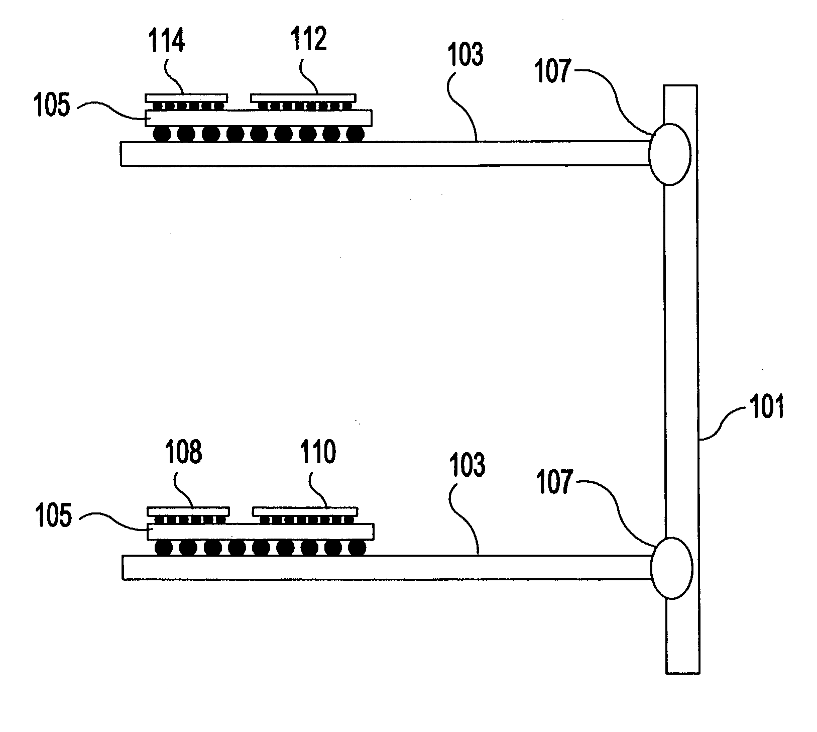
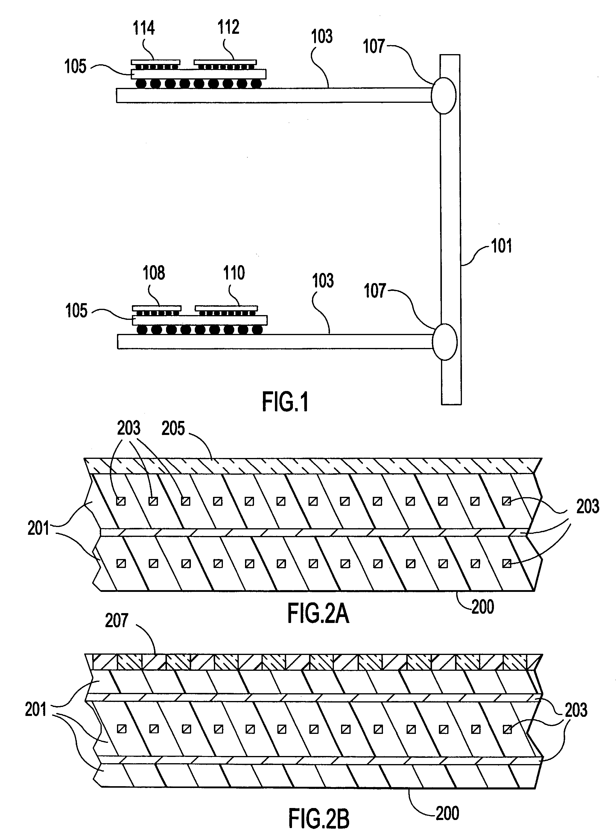
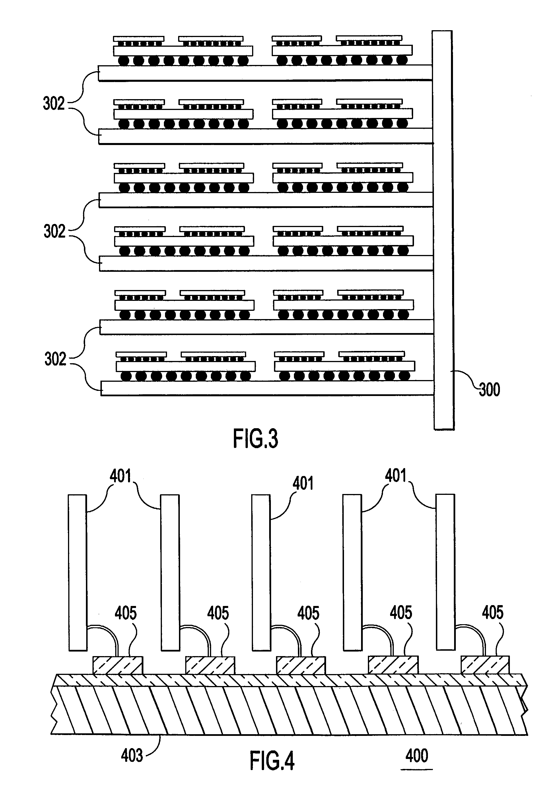
However, with the boards 302 connected to "tap points" along the backplane optical channels, some signal is lost at each tap point.
Clearly, the added work and expense has not provided for inclusion of more than a few more boards.
For thousand of signals (instead of tens of signals), the total power required is prohibitive.
Furthermore, such a 4 to 5 board system would be inflexible, unscalable beyond 5 boards.
Likewise removing 1 or 2 boards for a midrange system would not scale particularly easily either.
Signal integrity and radiation issues would arise in the infrastructure which is designed for the 4-5 board system.

Method used


Image

  • Method for in-situ continuity check on an optical bus
  • Method for in-situ continuity check on an optical bus
  • Method for in-situ continuity check on an optical bus

Examples


embodiment 900

[0051] FIG. 9A shows an example of an alternative embodiment grating structure 900 with like elements labeled identically. In this embodiment 900, the lasers 703, 705 are in the center of the chip 901 and a pair of identical photodiodes 902, 904 and gratings 906, 908 are located on either side of the lasers 703, 705. The two photodiodes 902, 904 are wired together (not shown) to act as a single photodiode. The advantage of this embodiment is that the photodiodes 902, 904 can sense light in the channel that was transmitted by this same chip, which may be used in testing.

[0052] Futhermore, this embodiment 900 lends itself to a simple optical continuity check 920 in FIG. 9B when the board it is inserted into the backplane, i.e., during a board self-test sequence. During the self test, the channels are held open in step 922 by other connected boards, i.e., no other boards have access to the optical bus as described in further detail hereinbelow. Then, each transceiver 900 on the board, ...

embodiment 1500

[0061] FIG. 15 shows an example of an alternate embodiment 1500 wherein a transceiver pair 1502, 1504 are mounted side by side on the backplane 1506 rather than stacked. In this embodiment, only the repeater chip 1504 is mounted in a flange 1508, where it couples to a plug (not shown). The backplane chip 1502, which couples to backplane wave guides, is joined to the backplane 1506 outside the socket 1508. The two transceivers 1502, 1504 are connected through backplane wiring 1510 at a sufficiently short distance to accommodate the desired speed.

embodiment 1600

[0062] FIG. 16 shows another example of an alternate embodiment 1600 wherein optical signals are contained within each board 1602, 1604. In this embodiment, electrical board signals in backplane wiring 1606 only travel a very short distance to the electro-optical transceiver 1608.


PUM


Abstract

A method of continuity checking an optical connection. An first optical source transmits an optical signal. A first optical receiver is checked for the optical signal. A second optical source transmits another optical signal. A second optical receiver checks for the other optical signal.

Description

[0001] The present application is a divisional of U.S. patent application Ser. No. 10 / 305,853 (Attorney Docket No. YOR9-2002-0310-US1) entitled "BACKPLANE ASSEMBLY WITH BOARD TO BOARD OPTICAL INTERCONNECTIONS AND A METHOD OF CONTINUITY CHECKING BOARD CONNECTIONS" and related to U.S. patent application Ser. No. 10 / 305,822 (Attorney Docket No. YOR9-2002-0309-US1) entitled "OPTICALLY CONNECTABLE CIRCUIT BOARD WITH OPTICAL COMPONENT(S) MOUNTED THEREON" both filed Nov. 27, 2002, and to U.S. patent application Ser. No. 10 / _____________(Attorney Docket No. YOR9-2002-0370-US1) entitled "METHOD FOR THE ASYNCHRONOUS ARBITRATION OF A HIGH FREQUENCY BUS IN A LONG LATENCY ENVIRONMENT" filed coincident herewith, all to Bozso et al., assigned to the assignee of the present invention and incorporated herein by reference.[0002] Field of the Invention[0003] The present invention generally relates to high-speed inter chip optical connections and more particularly to high speed optical inter board conn...

Claims


Application Information

Patent Timeline
IPC IPC(8): G02B6/42G02B6/122G02B6/36G02B6/43G06F13/40H04B10/12H04B10/135H04B10/14H04B10/2581
CPCG06F13/409G02B6/43G02B6/36
Inventor BOZSO, FERENC M.EMMA, PHILIP G.
Owner GLOBALFOUNDRIES INC
Learn More