Temperature measuring method and plasma processing apparatus

a temperature measurement and plasma processing technology, applied in the field of temperature measurement method and plasma processing apparatus, can solve the problems of damage to the temperature sensor, inability to achieve high-precision temperature measurement, and difficulty in directly applying the method of measuring the temperature of a semiconductor wafer or a susceptor in the above-described manner to the etching process

Inactive Publication Date: 2004-06-10
TOKYO ELECTRON LTD
View PDF4 Cites 12 Cited by
  • Summary
  • Abstract
  • Description
  • Claims
  • Application Information

AI Technical Summary

Problems solved by technology

This capacitance coupling may possibly cause damage to the temperature sensor 20 and the sheath 23 due to the passage of an electric current therethrough.
However, the increase in thickness of the insulative member 24 causes such a problem that high-precision temperature measurement is not possible.
However, it is difficult to directly apply the method of measuring the temperature of a semiconductor wafer or a susceptor in the above-described manner to the etching process or the like using the plasma.
This is because a radio frequency power leaks from a window portion in which a transparent member is inserted and a light from the plasma becomes a noise.
Further, the temperature in the actual course of the process cannot be measured precisely by the method of measuring the temperature in advance through the use of an unprocessed semiconductor wafer.
As described above, the plasma processing using the radio frequency power has such a problem that it does not allow precise temperature measurement.
The increasing use of the radio frequency power with a higher frequency makes this problem more serious.

Method used


Image

  • Temperature measuring method and plasma processing apparatus
  • Temperature measuring method and plasma processing apparatus
  • Temperature measuring method and plasma processing apparatus

Examples


Embodiment Construction

[0040] Hereinafter, an embodiment of the present invention will be explained in detail with reference to the drawings.

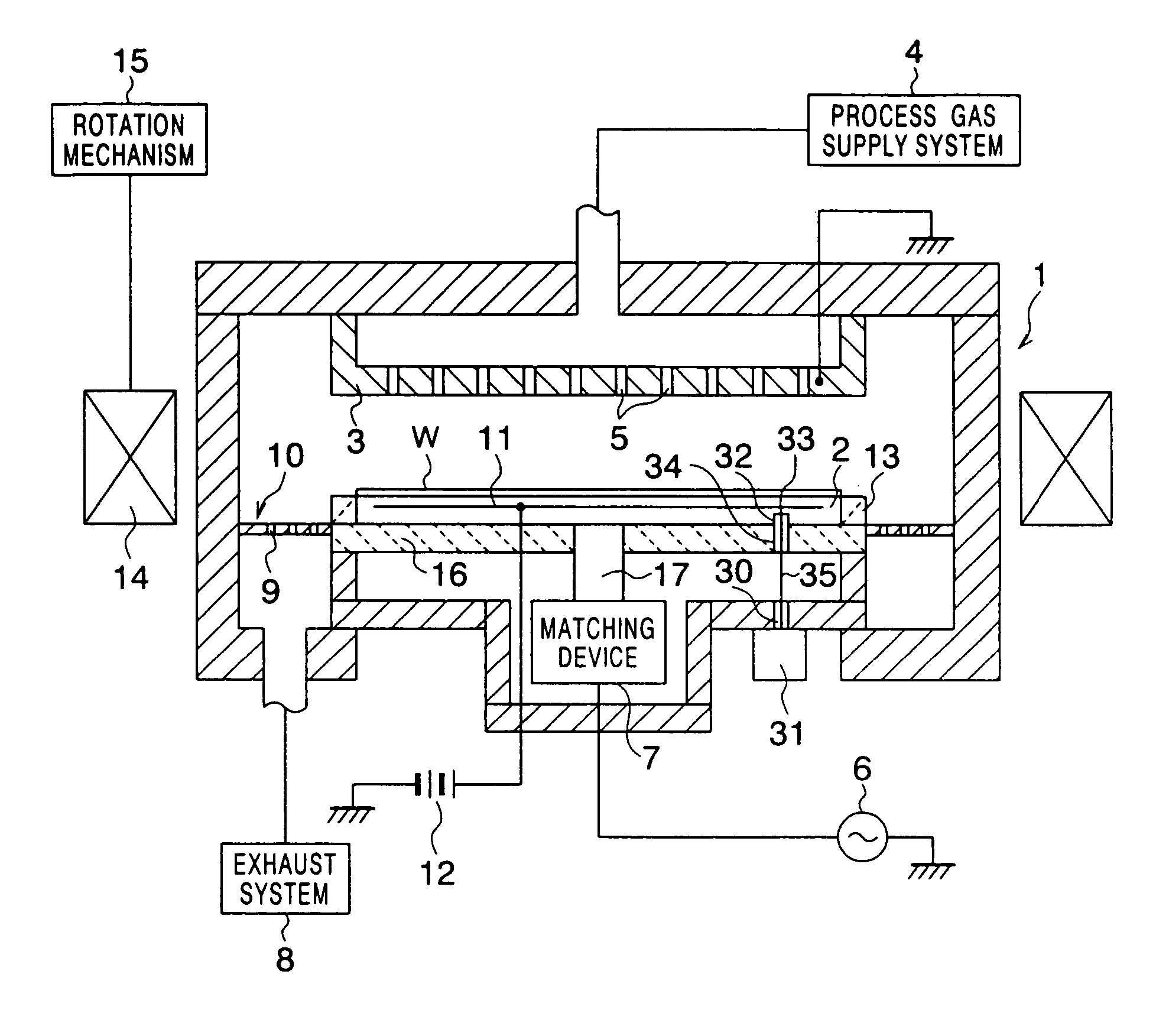
[0041] FIG. 1 schematically shows a general configuration of an entire plasma etching apparatus as a plasma processing apparatus according to an embodiment of the present invention. In FIG. 1, the same reference numerals are used to designate portions corresponding to those in the above-described plasma etching apparatus shown in FIG. 4.

[0042] In the plasma etching apparatus of this embodiment, a process vessel 1 is constituted of a conductive vessel using a conductive material such as, for example, aluminum whose surface is anodized. In the process vessel 1, a susceptor 2 also serving as a bottom electrode and a top electrode 3 facing this susceptor (bottom electrode) 2 are provided. This process vessel 1 is set to a ground potential and is designed so that a radio frequency power does not leak to an external part of the process vessel 1 when an etching process or t...


PUM

PropertyMeasurementUnit
frequencyaaaaaaaaaa
frequencyaaaaaaaaaa
frequencyaaaaaaaaaa

Abstract

A temperature measurement opening 30 is formed in a bottom portion of a process vessel 1 of a plasma etching apparatus, the temperature measurement opening 30 having a size not allowing a radio frequency power with a high frequency applied on a susceptor 2 to leak outside. To an external side of the temperature measurement opening 30, a radiation thermometer 31 is attached. The radiation thermometer 31 detects an infrared ray 35 emitted from the inside of a temperature measurement hole 32 formed on a rear face side of the susceptor 2 to measure the temperature of the susceptor 2.

Description

CROSS REFERENCE TO THE INVENTION[0001] This application is based upon and claims the benefit of priority from the prior Japanese Patent Application No. 2002-351314, filed on Dec. 3, 2002; the entire contents of which are incorporated herein by reference.[0002] 1. Field of the Invention[0003] The present invention relates to a temperature measuring method of measuring the temperature of, for example, a susceptor or the like disposed in a process vessel of a plasma processing apparatus and to the plasma processing apparatus.[0004] 2. Description of the Related Art[0005] In a semiconductor fabrication process and so on, a predetermined process has been conventionally applied on a substrate to be processed such as a semiconductor wafer in such a manner that a plasma is generated by a radio frequency power in a conductive vessel in which a space for the generation of the plasma therein is formed, and this plasma is made to act on the substrate to be processed.[0006] A parallel electrodes...

Claims


Application Information

Patent Timeline
Patent Type & Authority Applications(United States)
IPC IPC(8): G01J5/00C23C16/44C23C16/505G01J5/02G01J5/06H01J37/32H01L21/00H01L21/3065H05H1/46
CPCH01J37/32082H01L21/67248H01J2237/2001
Inventor HAYAMI, TOSHIHIROENDOH, SHOSUKE
Owner TOKYO ELECTRON LTD
Why Eureka
Try Eureka