Device for generating a reducing agent/air mixture

Inactive Publication Date: 2004-06-17
ROBERT BOSCH GMBH
View PDF4 Cites 22 Cited by
  • Summary
  • Abstract
  • Description
  • Claims
  • Application Information

AI Technical Summary

Problems solved by technology

As a result, the apparatus has a large structural size, and a connecting line is necessary between the feed pump and the mixing chamber, which makes production and assembly of the apparatus complicated and expensive, and there is the risk of leaks at the con

Method used


Image

  • Device for generating a reducing agent/air mixture
  • Device for generating a reducing agent/air mixture
  • Device for generating a reducing agent/air mixture

Examples


Example

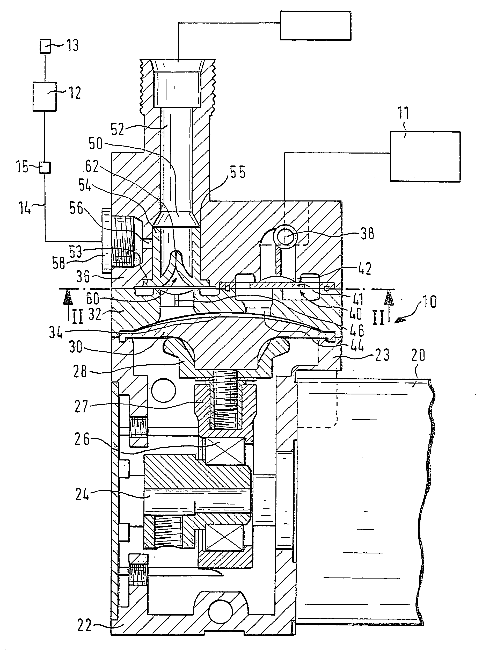
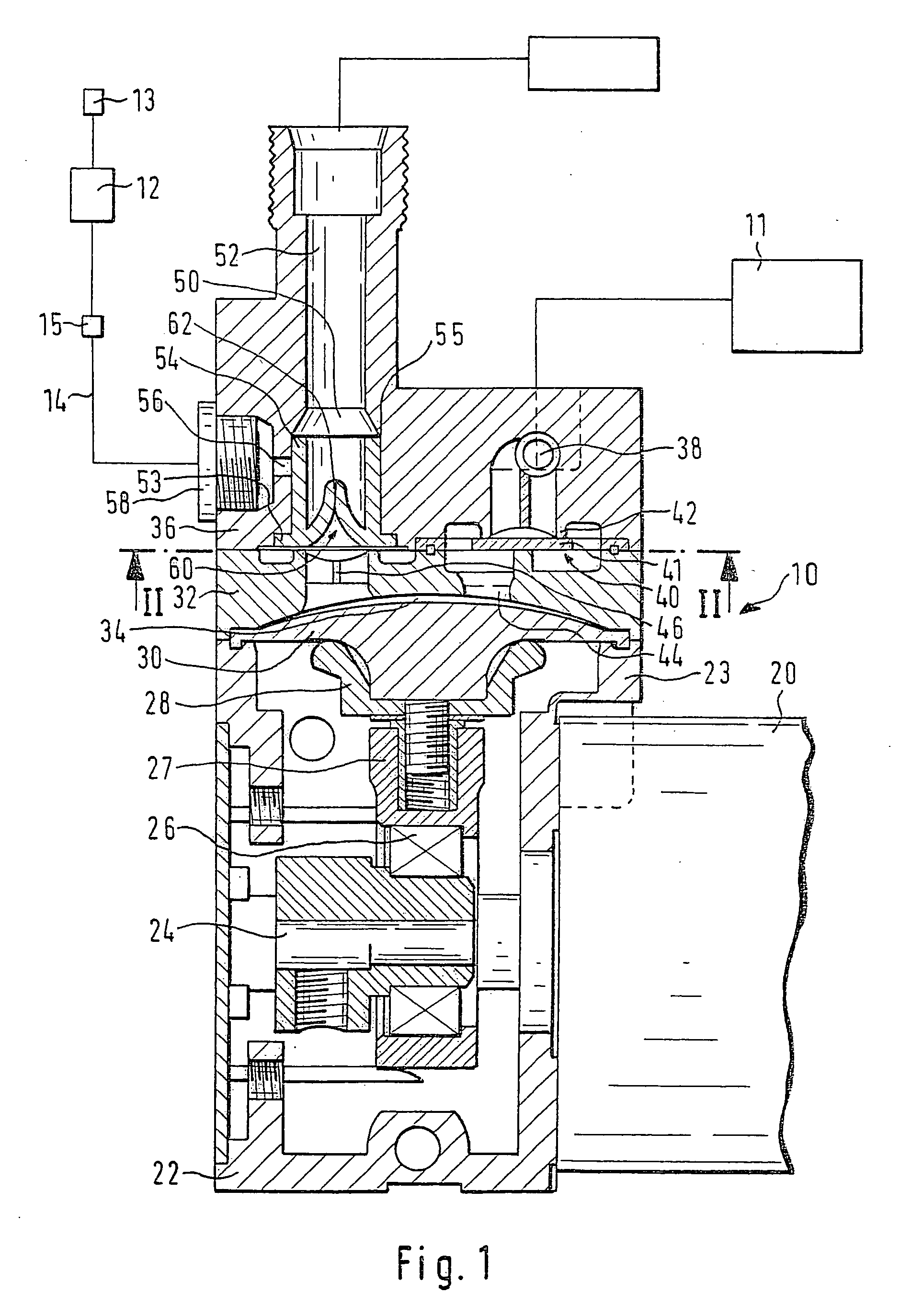
[0008] In FIGS. 1 and 2, an apparatus 10 for creating a mixture of reducing agent and air is shown, which is a component of a system for posttreatment of exhaust gas of a self-igniting internal combustion engine. The system has a container 11 for reducing agent, which can preferably be an aqueous urea solution or some other solution containing ammonia. The system furthermore has a compressed-air reservoir 12, into which air is pumped by a compressor 13 and in which pressure is generated. From the compressed-air reservoir 13, via a line 14, for instance in the form of a hose or in some other form for whose control a valve 15 is provided, compressed air is delivered to the apparatus 10. The apparatus 10 has a feed pump 16, by which reducing agent is pumped out of the container 11; in the apparatus 10, as will be described in further detail hereinafter, the reducing agent is mixed with the supplied compressed air, creating the mixture of reducing agent and air and optionally a wall fil...


PUM

PropertyMeasurementUnit
Pressureaaaaaaaaaa
Sizeaaaaaaaaaa

Abstract

The apparatus (10) for generating a mixture of reducing agent and air has a feed pump (16), by which reducing agent is pumped and which has a pump housing (22, 32). The apparatus (10) furthermore has a mixing chamber (50), into which reducing agent and air pumped by the feed pump (16) can be introduced; the mixing chamber (50) is embodied in a mixing chamber body (36). The mixing chamber body (36) communicates directly with the pump housing (22, 32) of the feed pump (16) and forms a cap of the pump housing (22, 32). The feed pump (16) has a drive shaft (24) for a feed element (30), which protrudes into the pump housing (22) of the feed pump (16), and the mixing chamber body (36) is disposed at least approximately radially to the drive shaft (24). The apparatus (10) has a compact structural size and only a slight reducing agent-filled idle volume.

Description

PRIOR ART[0001] The invention is based on an apparatus for generating a mixture of reducing agent and air as generically defined by the preamble to claim 1.[0002] One such apparatus is known from the literature: Dieselmotor-Management [Diesel Engine Management], Vieweg Verlag, 2nd Edition, 1998, page 31. This apparatus is part of a system for posttreatment of exhaust gases of internal combustion engines, especially self-igniting internal combustion engines. By adding a reducing agent to the exhaust gas, the effectiveness of a reducing catalytic converter for reducing nitrogen oxides in the exhaust gas can be improved. The apparatus has a feed pump, by which reducing agent is pumped and which has a pump housing. The apparatus has also a mixing chamber, into which reducing agent and air pumped by the feed pump can be introduced, in order to create the mixture of reducing agent and air. The mixing chamber is embodied in a mixing chamber body, which is disposed separately from the feed ...

Claims


Application Information

Patent Timeline
IPC IPC(8): B01D53/56B01F25/60B01D53/74F01N3/36F01N3/20F04B43/02
CPCB01F3/04099B01F5/0077B01F5/0471B01F15/0201Y02T10/24F01N3/2066F01N2610/02F01N2610/08B01F15/0237Y10T137/7889Y02T10/12B01F23/23B01F25/105B01F25/314B01F35/7174B01F35/71F01N3/20
Inventor HUBER, SVENMAYER, HANSPETER
Owner ROBERT BOSCH GMBH
Why Eureka
Try Eureka