
Recharbeable battery pack and manufacturing method thereof

Inactive Publication Date: 2004-06-17
MOBYPOWER
View PDF1 Cites 51 Cited by
  • Summary
  • Abstract
  • Description
  • Claims
  • Application Information

AI Technical Summary

Benefits of technology

[0006] Finally, this invention seeks to improve the battery's reliability by constructing a battery safety unit, along with rechargeable battery, into a single battery pack.

Problems solved by technology

Consequently, it is difficult to interchange rechargeable battery with the ordinary commercial battery, and several disposable batteries must be used in order to meet the voltage or electric current required by the portable electronic appliances.
In addition, even when several rechargeable batteries are used in order to obtain sufficient capacity and lengthen the usage time, one faces with a shortcoming that it takes a long time to recharge those rechargeable batteries.
Furthermore, there is a battery cell that combines multiple disposable batteries in the portable electronic appliances, but no rechargeable battery pack that meets the same standards has been developed.
The result is that interchange with the disposable battery cell is not possible, and accordingly, the battery life for the portable electronic appliances is short and impossible to recharge.

Method used


Image

  • Recharbeable battery pack and manufacturing method thereof
  • Recharbeable battery pack and manufacturing method thereof
  • Recharbeable battery pack and manufacturing method thereof

Examples


first embodiment

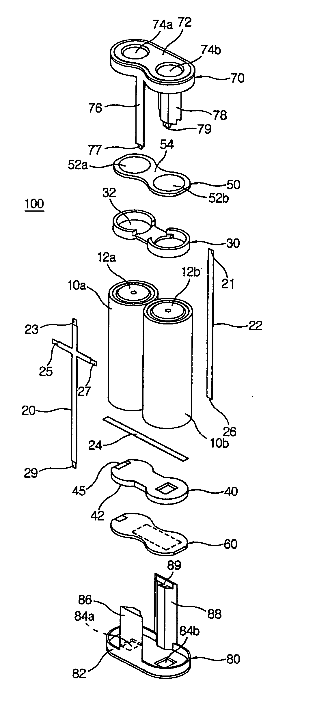
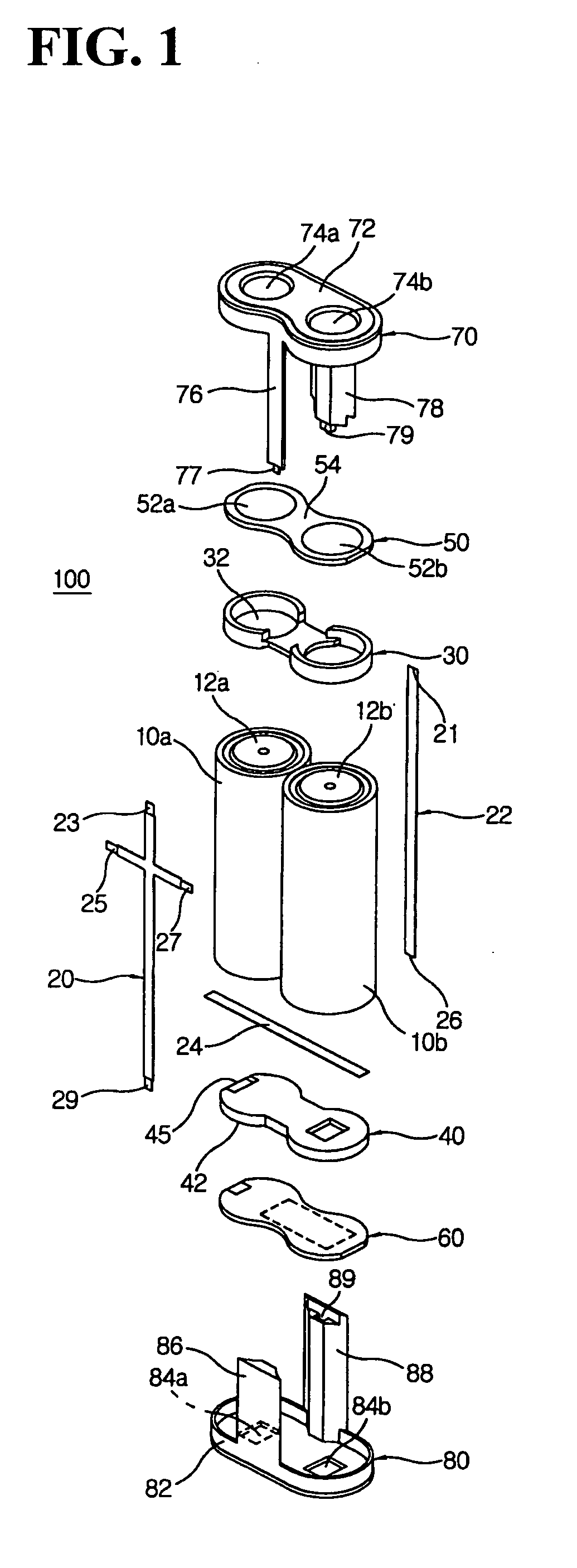
[0032] First Embodiment

[0033] FIG. 1 is a perspective view of the battery pack constructed according to the first embodiment for this invention. The battery pack (100) contains two individual batteries (10a, 10b) as well as connecting conductors which electrically connect these batteries. Individual batteries (10a, 10b) include Nickel Cadmium (Ni--CdO) batteries which use Ni(OH).sub.2 as the cathode, Cd as the anode and alkali aqueous solution as electrolytes, Nickel hydrogen (NiMH) batteries which use Ni(OH).sub.2 as the cathode, metal hydride (MH) as the anode and alkali aqueous solution as electrolytes, and Lithium Ion (Li-Ion) batteries which use carbon (C) or graphite as the anode, LiCoO.sub.2 as the cathode and Lithium-Salt organic solvent as electrolytes. However, it is advisable to use Lithium-Ion (Li-Ion) batteries for the individual batteries. Lithium-Ion (Li-Ion) batteries are 40-50% smaller than Nickel Cadmium batteries and 20-30% smaller than Nickel Hydrogen batteries. ...

second embodiment

[0061] Second Embodiment

[0062] FIG. 8 is a break-down perspective view of the battery pack (200) according to the second embodiment.

[0063] Cathode terminals and anode terminals of the individual batteries (210a, 210b) are connected among cathode terminals and among anode terminals respectively, and thereby the individual batteries, electrically connected to each other in a row, form the battery pack (200). These individual batteries are electrically connected by a plate-shaped connecting conductor (212) and a line-shaped sub-conductor (216). The sub-conductor (216) is connected to the connecting conductor (212) in order to have both cathode and anode output terminals formed at both sides of the upper and lower parts of the battery pack (200), whereas the lengthened sub-conductors (216) are each located at the opposite sides of the battery pack (200) so to form different electrodes at each side of the battery pack (200). Between the connecting conductor (212) and the sub-conductor (2...

first circuitry example

[0069] FIG. 11 is a block circuit diagram showing the battery safety unit (350) and the constant voltage circuit (360) which can be included in the battery pack constructed according to the first and second embodiments.

[0070] The battery safety unit (350) includes a voltage detector (352), the first comparator (354), the second comparator (356), and a cut-off switch (358). The battery safety unit serves to eliminate the problem of capacity decline of batteries which occurs when electrical current is continuously supplied from a charger even after an electric charging is completed (380) during the course of recharging the battery pack by applying the current to the battery pack (100, 200) by the external charger (380). For example, when Lithium ion batteries are charged above 4.5V, the electrolytes within the batteries are resolved into gas, which increases the internal pressure of the batteries and causes safety edge to go into action to reduce such pressure. This mechanism can be a...


PUM

PropertyMeasurementUnit
Timeaaaaaaaaaa
Timeaaaaaaaaaa
Timeaaaaaaaaaa

Abstract

Rechargeable battery pack interchangeable with ordinary commercial batteries, has a battery safety unit, at least two individual batteries that have a cathode and an anode and a circuit board that contains a battery safety unit designed to shut off the electric current to the battery cell when the current has been over-charged in the recharge electrode and to stop the discharge of the battery pack when the output voltage of the discharge electrode falls below a certain voltage. A cathode connecting conductor connects the recharge and discharge electrodes to the cathode terminals of the individual batteries, and an anode connecting conductor connects the recharge and discharge electrodes to the anode terminals of the individual batteries. A cover contains the circuit board and ties the individual batteries, the cathode connecting conductor, the anode connecting conductor and the circuit board as a single battery pack format in the individual battery's upper and lower bodies. At least one of the cathode connecting conductor and the anode connecting conductor is electrically connected to the circuit board. The battery pack of this invention can be, for example, made of lithium ion battery and used in portable electronic devices such as a digital camera.

Description

[0001] This invention generally relates to the rechargeable battery technology, and more particularly to the battery pack including several rechargeable batteries, that is interchangeable with ordinary commercial batteries and includes a battery safety unit (BSU).BACKGROUD ART[0002] Different from the disposable battery (such as mercury battery, Manganese battery, Alkaline battery and Lithium battery) that must be discarded once the stored energy has been exhausted, rechargeable battery can be reused by recharging the battery's exhausted electric energy from external sources and is presently in wide use. The demand for rechargeable battery in portable consumer electronics such as mobile phone, PDA, laptop computer and digital camera is increasing, mainly because rechargeable battery is reusable and has bigger capacity than disposable battery.[0003] Disposable battery is manufactured in one of the AAA, AA, C, or D standards and thus different from the standards for the rechargeable b...

Claims


Application Information

Patent Timeline
IPC IPC(8): H01M10/42H01M50/522H01M10/44H01M50/529H01M50/574
CPCH01M2/202H01M2/34Y10T29/49114H01M10/425H01M10/4207Y02E60/10H01M50/522H01M50/574H01M10/44
Inventor LEE, SUNG HUN
Owner MOBYPOWER
Features
  • Generate Ideas
  • Intellectual Property
  • Life Sciences
  • Materials
  • Tech Scout
  • Unparalleled Data Quality
  • Higher Quality Content
  • 60% Fewer Hallucinations
Learn More