Remote fluid level detection system

a technology of fluid level detection and remote detection, which is applied in the direction of liquid/fluent solid measurement, machines/engines, instruments, etc., can solve the problems of inaccurate information of the total amount of ammonia dispensed, inability to know the fluid level inside the tank, and degraded time efficiency, so as to achieve precise indication of internal fluid level and high resolution

Inactive Publication Date: 2004-07-08
RAVEN INDUSTRIES INC
View PDF35 Cites 34 Cited by
  • Summary
  • Abstract
  • Description
  • Claims
  • Application Information

AI Technical Summary

Benefits of technology

[0010] Fluid level information is available on a continuous basis as fluid application is occurring. This eliminates the current need to stop application to physically read the existing gauge mechanism on the field tank.
[0062] Since the gauge [30] reading will change at a faster rate at the high and low portions of the tank volume relative to the mid-portions of the tank volume, the tank module [40] of the present invention allows the fluid level refresh rate to be optimized for both performance and power saving. If fluid level data has changed sufficiently within the preset threshold

Problems solved by technology

When the farmer is applying the anhydrous ammonia, the fluid level inside the tank is not known because the size and orientation of the gauge face render it completely unreadable from the cab of the tractor.
A standard 1450 gallon anhydrous ammonia field tank is sufficient for only 40 acres of farmland, so this tedious task of determining the fluid level as the tank reaches empty is a recurring annoyance that results in degraded time efficiency.
Another shortcoming of the prior system, is that the total amount of dispensed ammonia is not accurately known until the tank has been emptied.

Method used


Image

  • Remote fluid level detection system
  • Remote fluid level detection system
  • Remote fluid level detection system

Examples


example 1

Input Button Designation and Use

[0075] The display module [200] interfaces with the user via three general purpose input buttons [206, 208, 210]. The input buttons [206, 208, 210] are located directly beneath the liquid crystal display [212]. The function of each input button [206, 208, 210] changes depending on the point in software flow. Each button's [206, 208, 210] function is made known to the user by utilizing the bottom row of characters of the liquid crystal display [212] to print directly above each button [206, 208, 210] what the corresponding button will cause the display module [200] to do at various points in software flow.

[0076] The display module [200] initiates operation with a welcome screen to indicate "power on" status while the internal circuitry is reset and stabilized. The welcome screen allows user to select one of two options. The left button [206] is depressed if the user wants to input tank size, implement size, or groundspeed calibration information. The r...

example 2

Determination of Fluid Level Compensation Due to Pitch and Roll

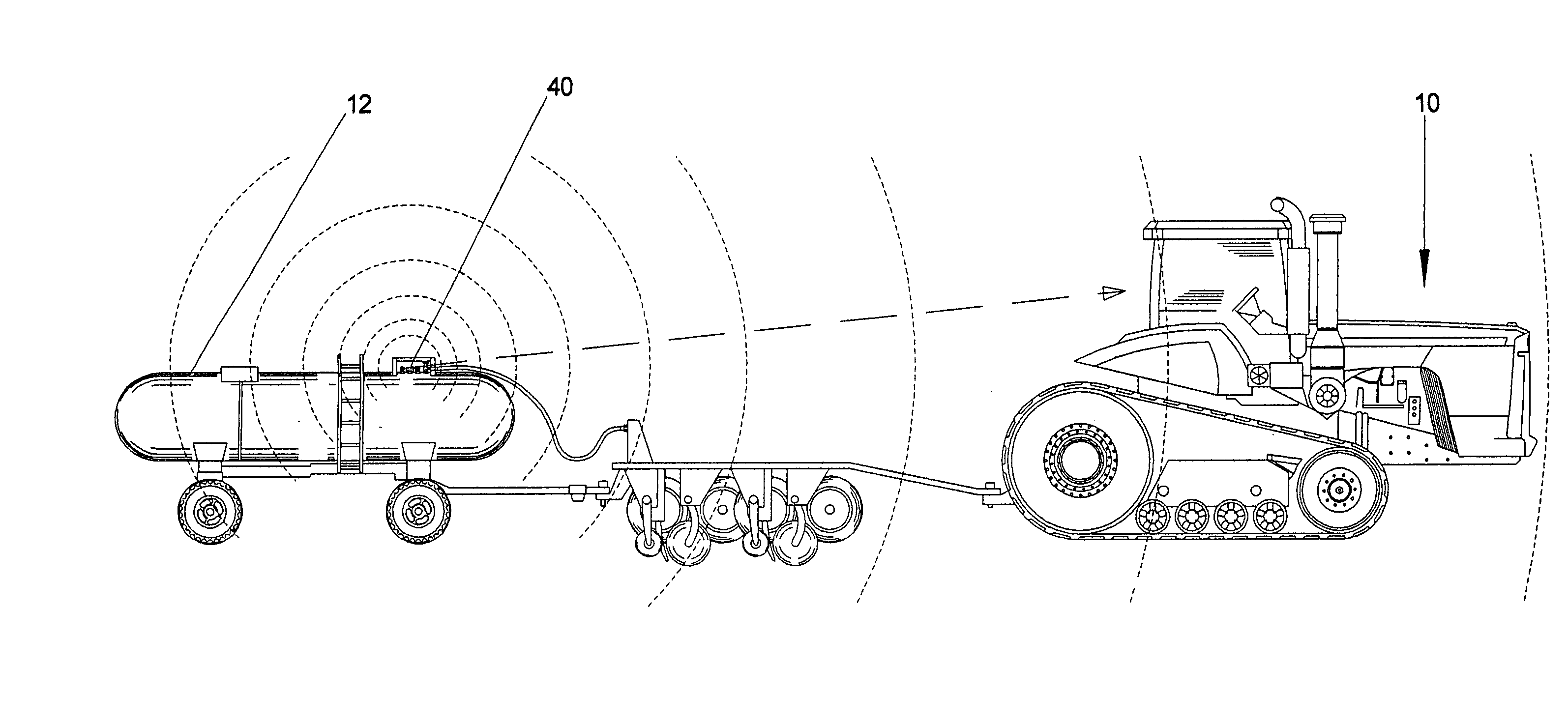
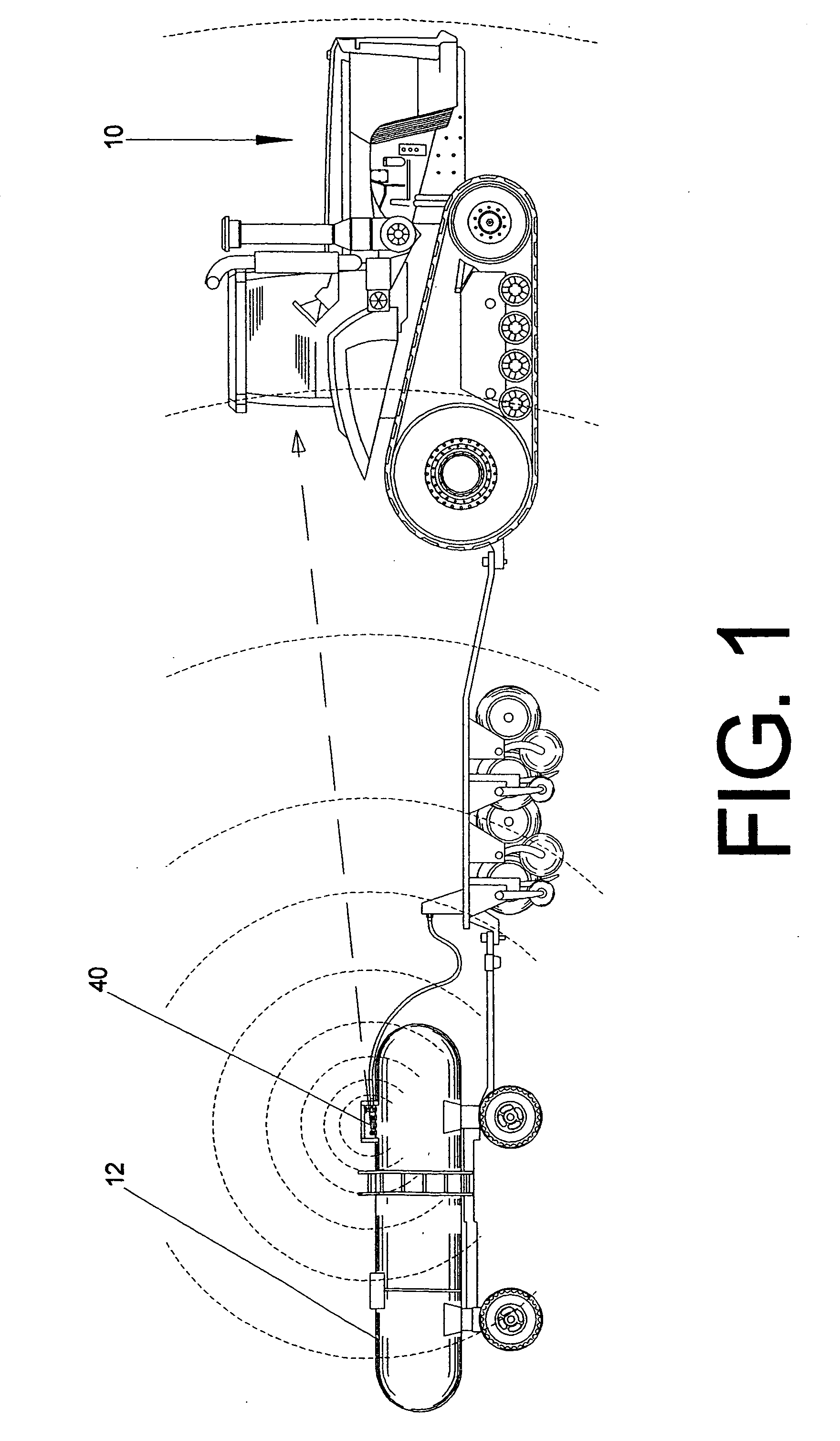
[0080] The tank module [40] is capable of measuring both pitch and roll measurements of the tank's [12] angle of incidence relative to the ground plane by means of a 2-axis electronic inclinometer [60]. Since most internal gauge mechanisms are mounted axially within the field tank [12], the pitch of the field tank [12] will have by far the largest effect on possible measurement errors associated with uneven terrain, as opposed to roll which would be encountered frequently in contour farming and does not have a significant effect on float position. The tank module [40] compensates for erroneous float positions due to pitch inclines or declines by combining the information from the electronic inclinometer [60] with the current averaged fluid level.

[0081] FIG. 23 details a fluid containing tank on an incline. As the tank goes up a hill, for instance, the inclinometer [60] will measure the angle of the field tank relative to...

example 3

Determination of "Sleep Time" Between Fluid Level Readings

[0082] The microcontroller varies the amount of time it sleeps between fluid level samples depending on the amount of fluid remaining in the tank as a means to conserve battery power, while enhancing performance and accuracy of fluid level measurements.

[0083] It is known, based on the cylindrical geometry of the tank, that for any given flow rate of fluid from the field tank, that the rate of movement of the float arm will be greater at the upper and lower portions of the tank than it will be in the mid-section. This is because most of the volume of the tank is contained within the mid-section of the tank, so there is a smaller change in fluid level for any given quantity of fluid dispensed. The sampling rate, or duration of time that the microcontroller "sleeps" between samples, is selected from a look-up table within the tank module's onboard memory. Suitably, ten different sample periods are available to the microcontrolle...


PUM


Abstract

A remote two-module electronic fluid monitoring system to be used as an agricultural aid in the application of a fluid to a field. A tank module sits atop a field tank and monitors internal fluid level. Fluid level detection is achieved by tracking the position of an embedded permanent magnet associated with a given internal fluid level within an existing float gauge mechanism. An integrated circuit capable of precisely detecting the orientation of magnetic fields senses the angular position of an existing magnet and outputs an angular field reading to an interfaced microcontroller which then translates angular reading to fluid level. The tank module contains a radio frequency transmitter which then sends fluid level information to a display module mounted within the tractor cab. The display module receives the signal from the tank module and reports to the user the present fluid level remaining in tank via a liquid crystal display.

Description

[0001] This application claims the benefit of the filing date of U.S. Provisional Application No. 60 / 265,317.BACKGROUND OF INVENTION[0002] This invention relates to a remote fluid level detection system. The system uses magnetic detection to determine the fluid level in a confined vessel. Suitably, the invention is utilized with anhydrous ammonia field tanks.[0003] Anhydrous ammonia (NH.sub.3) is a substance used in agriculture as a fertilizer because of its high nitrogen content. Typically, anhydrous ammonia is applied to fields in the fall after the crop has been harvested to replenish the nutrients for the next season. The application of anhydrous ammonia involves the use of a field tractor, a field implement that is pulled behind the tractor and a large anhydrous ammonia tank that is pulled behind the implement. This creates a relatively long, train-like configuration of machinery.[0004] Anhydrous ammonia is a multi-phase chemical that, when stored under pressure in the field ta...

Claims


Application Information

Patent Timeline
Patent Type & Authority Applications(United States)
IPC IPC(8): G01F23/38
CPCG01F23/38
Inventor SORENSON, CHAD MICHAEL
Owner RAVEN INDUSTRIES INC
Why Eureka
Try Eureka