Air-conditioning system

a technology of air-conditioning system and air-conditioning system, which is applied in the field of air-conditioning system, can solve the problems of significant energy wastage, achieve the effects of simplifying and speeding up installation, reducing installation costs, and reducing energy consumption and space occupation

Active Publication Date: 2004-08-05
UNIFLAIR IND SPA
View PDF1 Cites 40 Cited by
  • Summary
  • Abstract
  • Description
  • Claims
  • Application Information

AI Technical Summary

Benefits of technology

0019] to integrate the heating and cooling systems, reducing energy consumption and space occupied;
0020] to simplify and speed up installation and to reduce in...

Problems solved by technology

High-technology areas, such as computer rooms and control rooms, normally require air conditioning even during the winter since the heat produced by the e...

Method used


Image

  • Air-conditioning system
  • Air-conditioning system
  • Air-conditioning system

Examples


Embodiment Construction

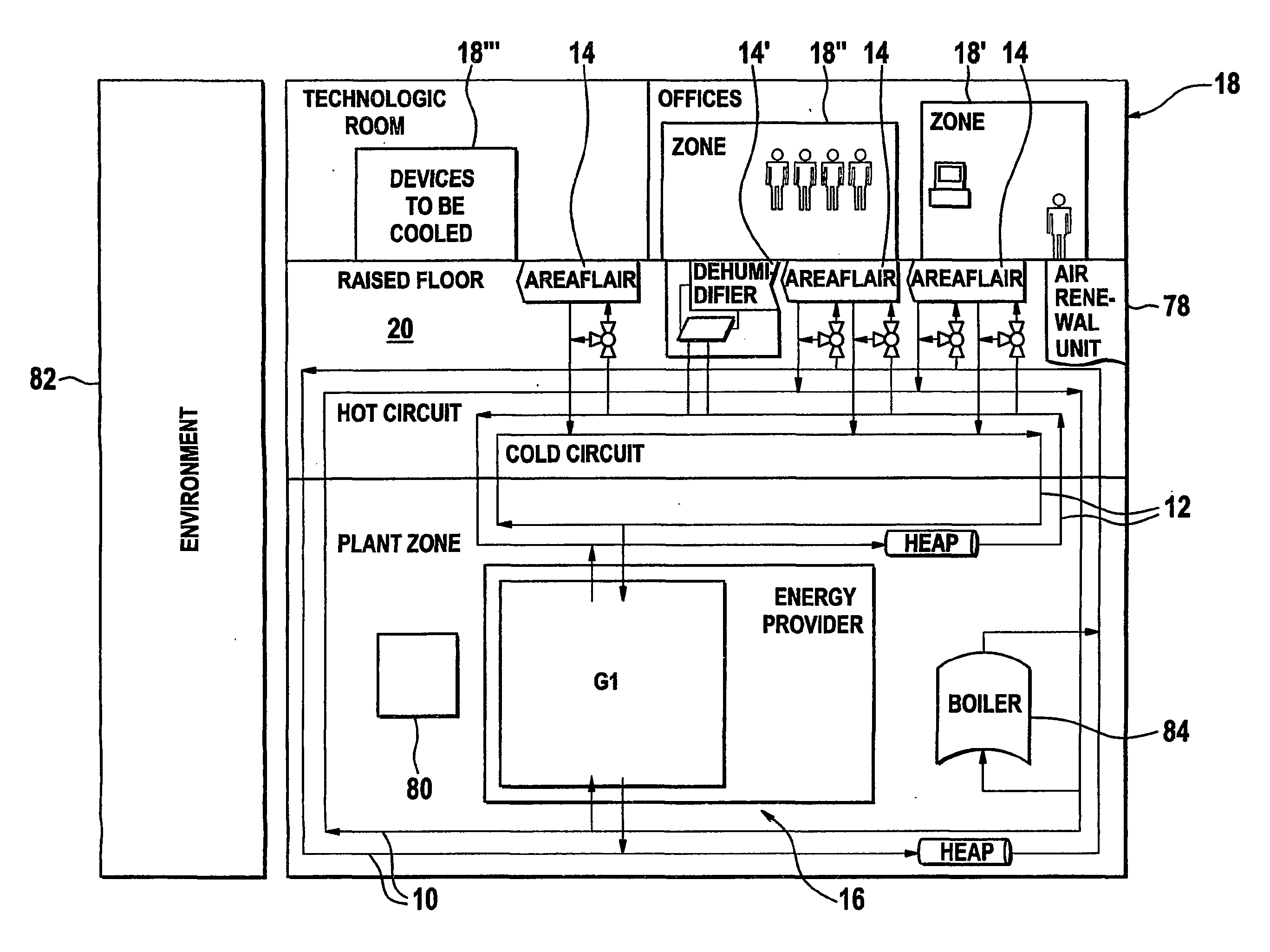
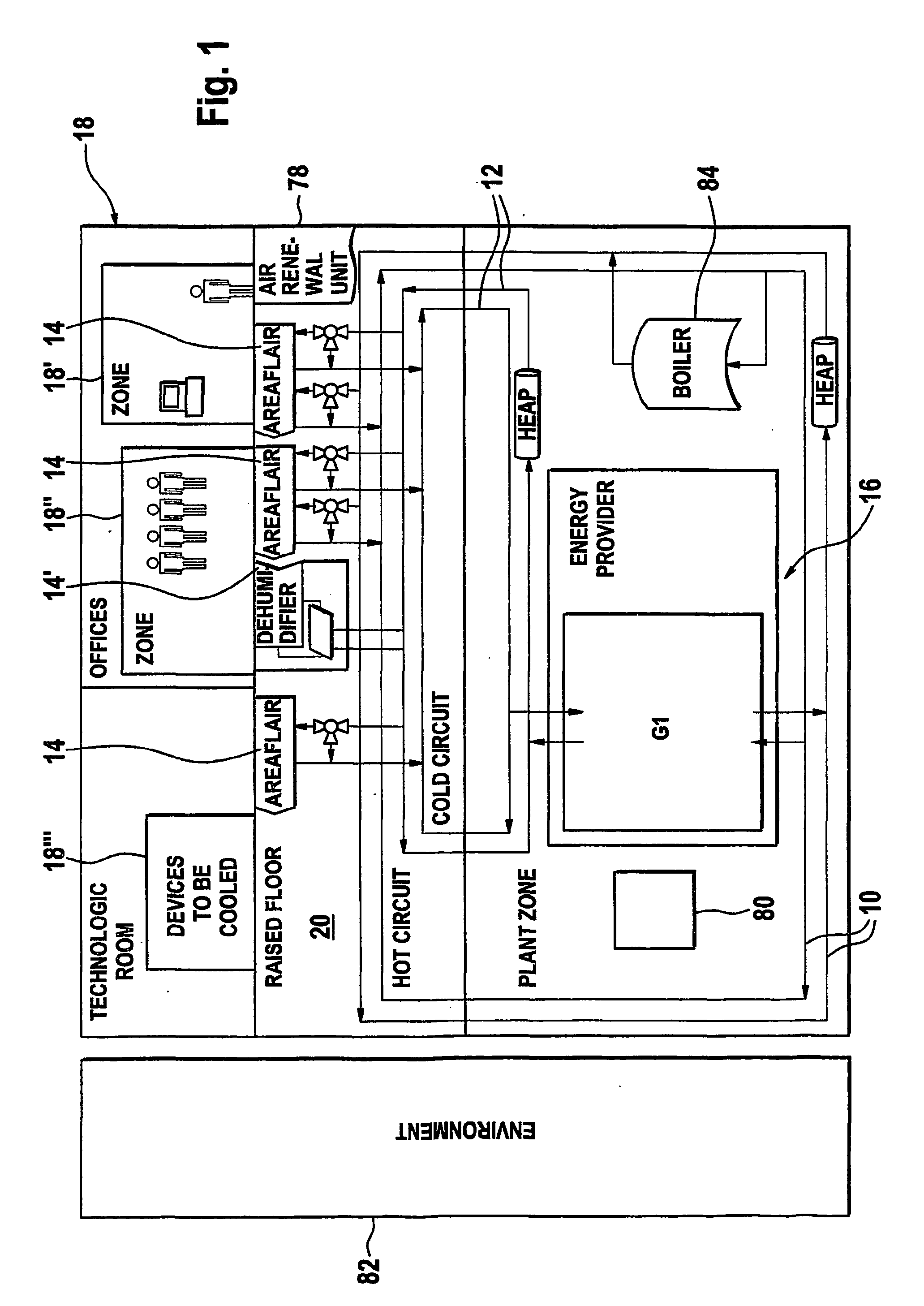
[0033] FIG. 1 shows schematic diagram of an air-conditioning system in accordance with the present invention. This system comprises a hot water distribution circuit 10 and a cold (or chilled) water distribution circuit 12, a plurality of terminal air conditioning units 14, which are also called zone terminal units, and a heat / cooling generator 16 also called "energy provider" 16.

[0034] The hot and cold water distribution circuits 10, 12 are conceived as closed peripheral energy distribution loops in a building 18. Various zones 18', 18", 18'" of the building 18 require cooling and / or heating energy according to their specific needs. The whole air-conditioning system is conceived with a similar logic to that of electrical energy distribution: cold and hot water distribution networks are installed in the building 18 and then, according to individual needs, local terminal units 14 draw on the primary distribution to guarantee temperature and humidity control in the different zones 18',...


PUM


Abstract

An air-conditioning system for a building comprises a hot water distribution circuit (10), a cold water distribution circuit (12) and several terminal air conditioning units (14). Each of these terminal air conditioning units (14) comprises a fan (40) for blowing air in a space of the building, a heating coil (42) connected to the hot water distribu-tion circuit (10) and/or a cooling coil (44) connected to the cold water distribution circuit (12). At least one ambient temperature control system allows to control heating power of the heating coils and cooling power of the cooling coils. The system further includes a calorific energy management system (80) with a heat pump for transferring calorific energy: a) from the cold water distribution system to the hot water distribution system; b) from the cold water distribution system to atmosphere; and c) from the atmosphere to the hot water distribution system. The calorific energy management system (80) is capable of managing the calorific energy transfers with a three level control system so as to optimise energy consumption.

Description

[0001] The present invention relates to an air-conditioning system.[0002] Modern buildings generally have large areas of glass and a wide range of internal temperature requirements, with both internally- and externally-generated heat loads. This diversity necessitates zone temperature control and high levels of air purity in order to ensure adequate comfort levels even with high occupation densities of people and equipment. Internally generated heat loads contribute to a large extent to the total cooling load or the total heating load. The main internal heat sources being electrical and electronic equipment and high illumination densities.[0003] Localised climate control becomes necessary in large open-plan areas where individual workstations or equipment positions may require different temperatures. It is becoming more and more common to find people and equipment in the same office, requiring variation in thermal provision both in terms of Watts per square metre and seasonal change...

Claims


Application Information

Patent Timeline
IPC IPC(8): F24F1/00F24F3/08F24F5/00F24F11/02F24F12/00
CPCF24F3/08Y02B30/542F24F12/00Y02B30/54
Inventor CATZEL, PINCUS
Owner UNIFLAIR IND SPA
Why Eureka
Try Eureka