Quick recharge energy storage device, in the form of thin films

a technology of energy storage device and thin film, which is applied in the direction of secondary cell servicing/maintenance, sustainable manufacturing/processing, flat cell grouping, etc., can solve the problems that the charging time of micro-batteries does not constitute an obstacle to their use in a large number of applications, and none of these devices can be integrated into a chip, so as to achieve the effect of not reducing the energy capacity

Inactive Publication Date: 2004-08-19
COMMISSARIAT A LENERGIE ATOMIQUE ET AUX ENERGIES ALTERNATIVES
View PDF5 Cites 91 Cited by
  • Summary
  • Abstract
  • Description
  • Claims
  • Application Information

AI Technical Summary

Benefits of technology

0005] The object of the invention is to provide an energy storage device not presenting the above drawbacks and, more part

Problems solved by technology

However none of these devices can be integrated in a chip.
The charging time of micro-batteries does however constitute

Method used


Image

  • Quick recharge energy storage device, in the form of thin films
  • Quick recharge energy storage device, in the form of thin films
  • Quick recharge energy storage device, in the form of thin films

Examples


Embodiment Construction

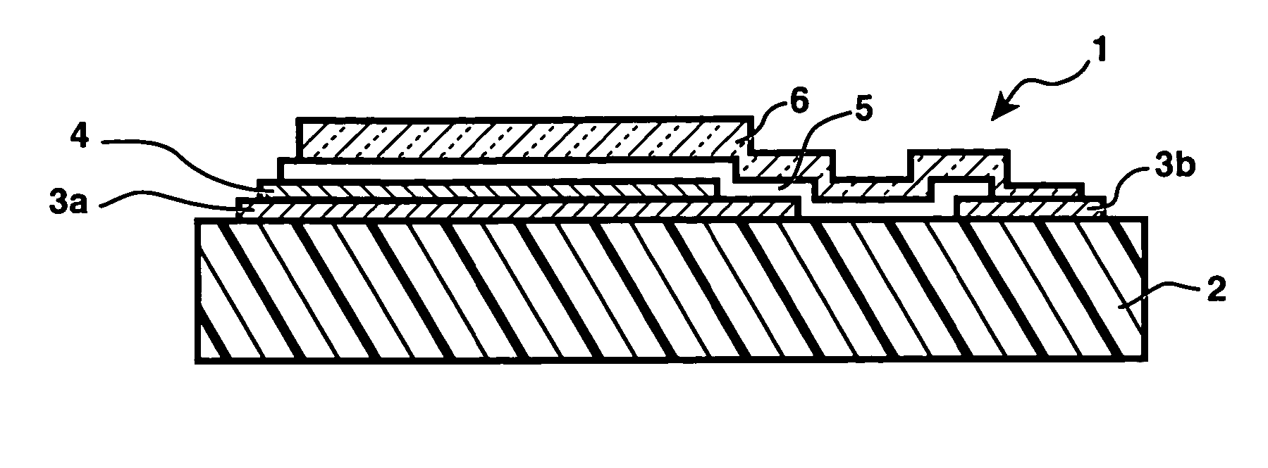
[0014] The operating principle of a micro-battery is based on insertion and de-insertion of an alkaline metal ion or a proton in the positive electrode of the micro-battery, preferably a lithium ion Li.sup.+ originating from a metallic lithium electrode. In FIG. 1, the micro-battery is formed on an insulating substrate 2 by a stack of layers obtained by CVD or PVD, respectively constituting two current collectors 3a and 3b, a positive electrode 4, a solid electrolyte 5, a negative electrode 6 and possibly an encapsulation (not shown).

[0015] The elements of the micro-battery 1 can be made of various materials:

[0016] The metal current collectors 3a and 3b can for example be platinum (Pt), chromium (Cr), gold (Au) or titanium (Ti) based.

[0017] The positive electrode 4 can be formed by LiCoO.sub.2, LiNiO.sub.2, LiMn.sub.2O.sub.4, CuS, CuS.sub.2, WO.sub.yS.sub.z, TiO.sub.yS.sub.z, V.sub.2O.sub.5 or V.sub.3O.sub.8 and lithium forms of these vanadium oxides and metal sulfides. Depending on...


PUM


Abstract

The quick recharge energy storage device has a sufficient capacity due to the combination of a micro-battery and at least one micro-supercapacitor connected between two terminals of an integrated circuit. The integrated circuit, powered by the micro-battery, monitors high-speed (less than one second) charge of the micro-supercapacitors from an external energy source. The micro-supercapacitor can be connected in parallel with the micro-battery so as to subsequently recharge the micro-battery during the necessary time. The micro-battery provides a sufficient energy capacity, while the micro-supercapacitors allow high recharging speeds compatible with various applications (smart cards, smart labels, micro-system power supply, etc . . . ). The micro-battery and micro-supercapacitors are preferably formed on the same substrate, either side by side or stacked. Series connection of several micro-supercapacitors provides sufficient voltage for charging the micro-battery.

Description

[0001] The invention relates to an energy storage device comprising a battery and at least one supercapacitor.STATE OF THE ART[0002] Hybrid storage devices associating a supercapacitor and a battery connected in parallel have in particular been described in U.S. Pat. No. 6,117,585, U.S. Pat. No. 6,187,061, and the article "Le supercondensateur et la batterie se marient pour fournir de l'nergie" by A. Rufer (Electronique, CEP Communication, Paris n.degree.100, February 2000). These devices combine the advantages of their two components and notably enable a large quantity of energy to be stored while having a large instantaneous power available. However none of these devices can be integrated in a chip.[0003] Furthermore, a lithium micro-battery, in the form of thin films, the thickness whereof is comprised between 7 .mu.m and 30 .mu.m (preferably about 15 .mu.m) and which is formed by chemical vapor deposition (CVD) or physical vapor deposition (PVD) is for example described in the d...

Claims


Application Information

Patent Timeline
IPC IPC(8): H01G9/28H01G4/40H01G9/00H01G9/025H01G9/155H01M10/38H01M10/44
CPCH01G4/40Y02E60/13H01G9/155Y02P70/50H01G11/08H01G11/10H01G11/26H01G11/72H01G11/82
Inventor SALOT, RAPHAEL
Owner COMMISSARIAT A LENERGIE ATOMIQUE ET AUX ENERGIES ALTERNATIVES
Why Eureka
Try Eureka