Magnetic encoder and wheel support bearing assembly using the same

a technology of magnetic encoder and bearing assembly, which is applied in the direction of magnets, magnet bodies, instruments, etc., can solve the problems of affecting the quality of the magnetic material used in the processing machine, the sensitivity of the processing machine to be damaged, and the amount of powdery rare earth magnetic material to be blended cannot be increased

Inactive Publication Date: 2004-08-26
NTN CORP
View PDF6 Cites 6 Cited by
  • Summary
  • Abstract
  • Description
  • Claims
  • Application Information

AI Technical Summary

Problems solved by technology

However, where the matrix is an elastomer or a plastomer, the amount of the powdery rare earth magnetic material to be blended cannot be increased because of the following problems found occurring during a process of mixing the matrix with the powdery rare earth magnetic material.
Problems similar to those with the use of the powdery rare earth magnetic material equally apply to that of the powdery ferrite magnetic material.
(a) If the amount of the powdery magnetic material to be blended is large, a processing machine (particularly a kneading machine) is apt to be damaged considerably.
The running torque tends to be so large as to impose an excessive load on the processing machine and/or, as a result of contact with the powdery magnetic material that is generally hard and tough, rolls used in the processing machine are susceptible to wear, accompanied by considerable damage.
(b) By the effect of heat evolved during the processing (blending and kneading), the powdery magnetic material is susceptible to oxidization, resulting in eventual degradation of the magnetic characteristic.
Also, when the conventional magnetic encoder made of an elastomer or a plastomer is applied in the rotation detecting device incorporated in the wheel support bearing assembly, particulate matters such as sand particles or grit tend to be trapped in between the magnetic encoder and the sensor confronting the magnetic encoder, resulting in damage to the surface of the magnetic encoder.
However, it has been found that even

Method used


Image

  • Magnetic encoder and wheel support bearing assembly using the same
  • Magnetic encoder and wheel support bearing assembly using the same
  • Magnetic encoder and wheel support bearing assembly using the same

Examples


Embodiment Construction

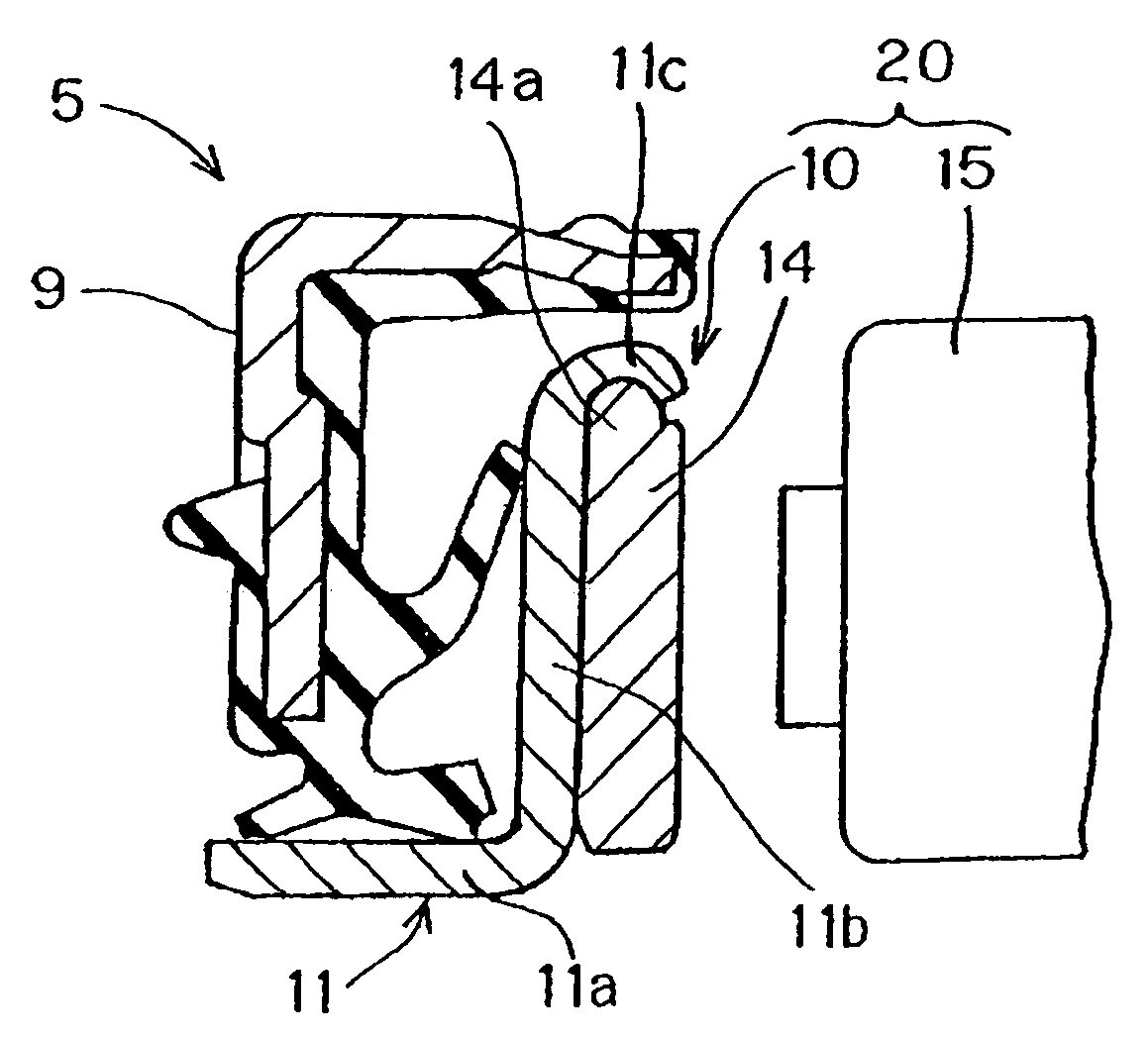
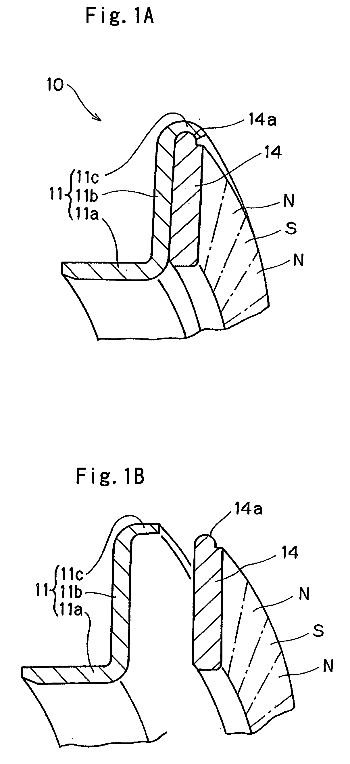
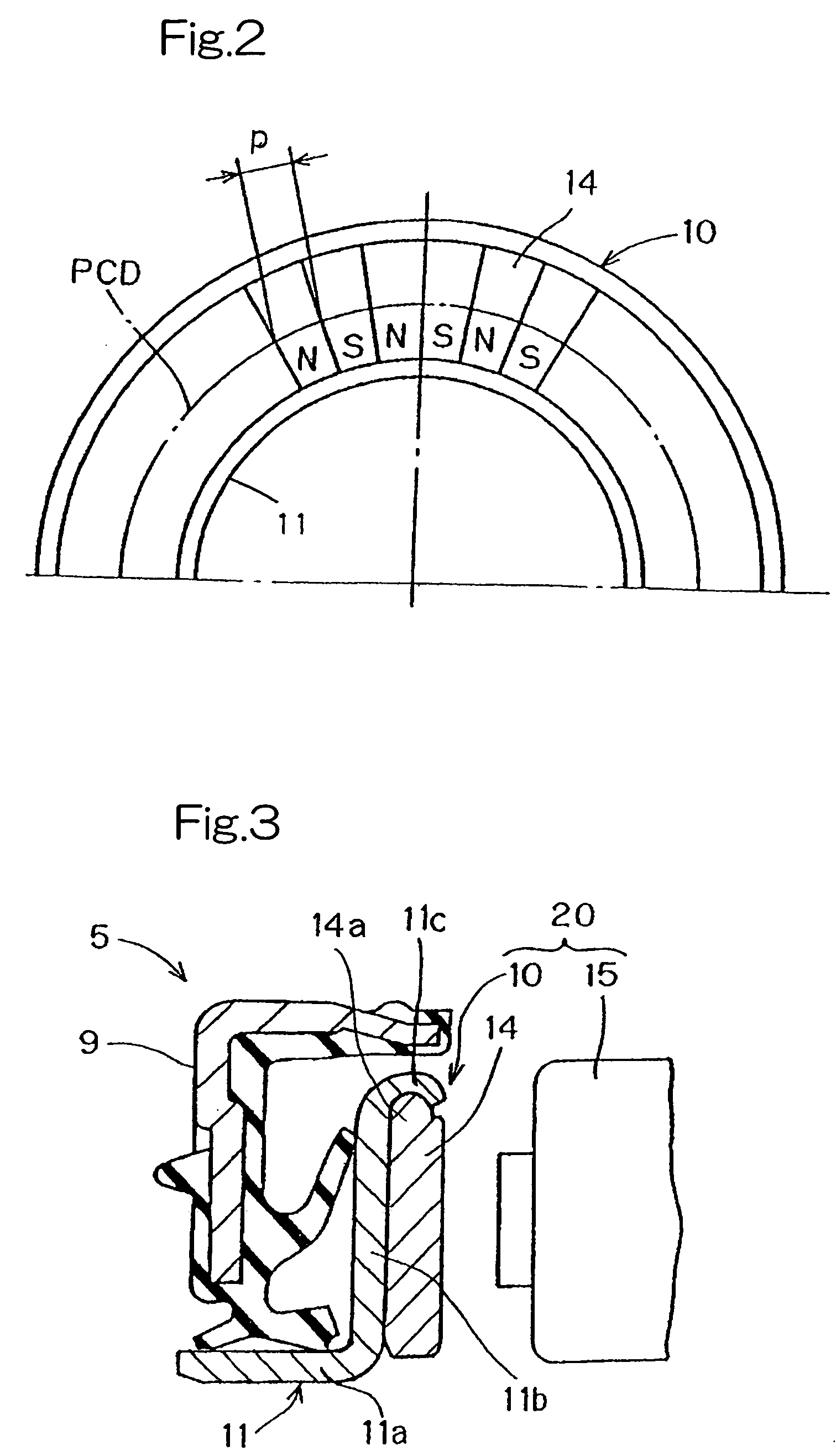
[0055] Referring first to FIGS. 1A to 3, there is shown a magnetic encoder 10 according to a first preferred embodiment of the present invention. The magnetic encoder 10 shown therein includes an annular core metal 11 made of a metallic material and an annular multi-pole magnet 14 secured to an annular surface of the core metal 11 so as to extend circumferentially thereof. The multi-pole magnet 14 is a member having a plurality of opposite magnetic poles N and S magnetized so as to alternate in a direction circumferentially thereof and may be in the form of a magnetic ring. The opposite magnetic poles N and S alternate circumferentially of the multi-pole magnet 14 at intervals of a predetermined pitch p as measured along the pitch circle diameter (PCD) shown in FIG. 2. The magnetic encoder 10 of the structure described above is fitted to a rotating member (not shown) and cooperates with a magnetic sensor 15 disposed in face-to-face relation with the multi-pole magnet 14 to detect th...


PUM


Abstract

To provide a magnetic encoder which can be assembled having a thin-walled structure while securing an excellent detection sensitivity and which can provide an excellent moldability by suitably selecting materials, the magnetic encoder is provided which includes a multi-pole magnet 14 having a plurality of opposite magnetic poles alternating in a direction circumferentially thereof, and a core metal 11 for supporting the multi-pole magnet. The multi-pole magnet 14 contains a powdery magnetic material mixed in an amount within the range of 20 to 90 vol. % relative to the total volume of the multi-pole magnet 14. The multi-pole magnet 14 may be a sintered magnet.

Description

[0001] 1. Field of the Invention[0002] The present invention relates to a magnetic encoder for use with a rotation detecting device for detecting the number of revolutions of one of bearing components rotatable relative to each other and also to a wheel support bearing assembly utilizing such magnetic encoder. The magnetic encoder to which the present invention pertains is suitably incorporated in the rotation detecting device of a kind utilized in association with an automobile anti-skid brake system for detecting the number of revolutions of at least one of front and rear wheels of an automotive vehicle.[0003] 2. Description of the Prior Art[0004] The rotation detecting device for use in association with the anti-skid brake system for minimizing the hazard of an automotive vehicle being skidded on a road surface has hitherto been assembled in a number of structures. In general, however, the conventional rotation detecting device of the kind referred to above includes a serrated ro...

Claims


Application Information

Patent Timeline
IPC IPC(8): G01D5/14G01D5/16G01D5/245G01P3/44G01P3/487H01F1/09
CPCF16C33/7879G01D5/145G01D5/2451G01P3/443F16C41/007H01F1/086H01F1/09H01F1/11H01F7/0221G01P3/487F16C2326/02F16C19/184F16C19/185G01D2205/80
Inventor NAKAJIMA, TATSUOOOHIRA, KOUYAMATSUI, ARITOMURAKAMI, KAZUTOYO
Owner NTN CORP
Why Eureka
Try Eureka