Elongated bumper bar with sections twisted rotationally about the axis of elongation and method of making the same

Inactive Publication Date: 2004-09-02
NOBLE ADVANCED TECH
View PDF16 Cites 20 Cited by
  • Summary
  • Abstract
  • Description
  • Claims
  • Application Information

AI Technical Summary

Benefits of technology

0008] To improve this situation, the present invention contemplates a box-shaped or C-shaped bumper bar, made by a conventional rolling process, which has certain of its sections twisted about the longitudinal axis of the bar so that the forward faces of the bar at these twisted sections are inclined relative to the vertical to more closely match the mating

Problems solved by technology

However, the goal of employing a bumper bar with a conventional boxlike configuration with opposed vertical sidewalls, one connected to the frame and the other to the fascia, and with fascias employing non-vertical surfaces, is di

Method used


Image

  • Elongated bumper bar with sections twisted rotationally about the axis of elongation and method of making the same
  • Elongated bumper bar with sections twisted rotationally about the axis of elongation and method of making the same
  • Elongated bumper bar with sections twisted rotationally about the axis of elongation and method of making the same

Examples


Embodiment Construction

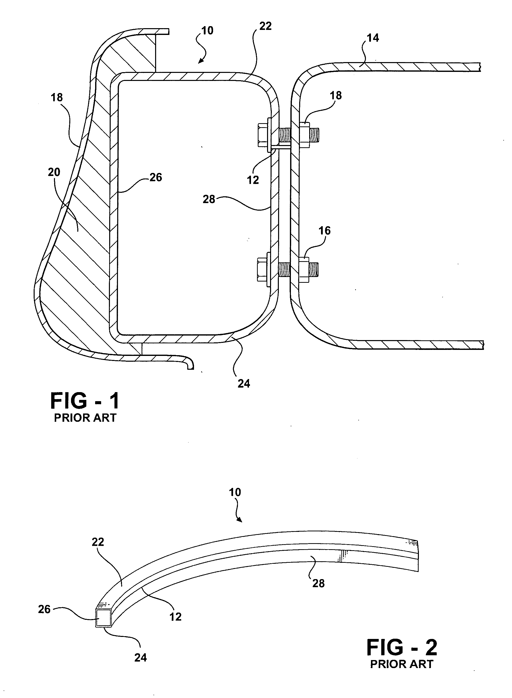
[0020] The present invention is directed toward a bumper bar system of the general type commonly used in automobiles and light trucks and illustrated in FIG. 1. These systems employ a bumper bar 10 which is usually produced by rolling sheet steel to form a generally box-like configuration which is elongated in the direction normal to the plane of the drawing. The box may be completely closed, as illustrated in FIG. 1, which is usually achieved by securing the free edges of the box as at 12 by welding, seaming or a similar process. Alternatively, the edges may be left unsecured, achieving a generally "C" cross section.

[0021] The bumper bar 10 is typically secured to the vehicle by attaching it to a pair of side rails 14 of the vehicle frame (only one of which is shown in FIG. 1) by bolts 16 or other attachment means, at a pair of spaced points inwardly from the ends of the bumper bar 10. The forward side of the bumper system is covered by a plastic fascia 18 which forms the outer vis...


PUM

PropertyMeasurementUnit
Elongationaaaaaaaaaa
Transition temperatureaaaaaaaaaa

Abstract

A bumper system for an automotive vehicle includes a rolled steel tube having a box or C-shaped cross section fixed to the forward ends of the side rails of the vehicle so as to extend transversely to the vehicle's longitudinal axis. The forward surface of the vehicle is formed by a plastic fascia which may have sloped surfaces for styling or aerodynamic reasons. The space between the forward end of the bumper bar and the fascia is filled with foam intended to absorb energy in an impact. To better match the sloped sections of the fascia, certain sections of the bumper bar are twisted about the longitudinal axis of the bar to create surfaces inclined relative to the vertical. The bars are formed by roll forming a steel web into an elongated member having generally vertical opposed faces. A section of the rolled member is heated above a metallurgical transition temperature. Then sections to be inclined are twisted about the longitudinal axis of the bumper bar in a die forming station and are then quenched to form a hardened steel member.

Description

[0001] This application claims priority of U.S. Provisional Patent Application Serial No. 60 / 435,410 filed Dec. 20, 2002, which is incorporated herein by reference.[0002] I. Field of the Invention[0003] This invention relates to bumper systems for vehicles and more particularly to a unique bumper bar and method for making the same for use in a bumper system including an exterior fascia having inclined sections, a bumper bar secured to extending frame sections of the vehicle, and plastic foam between the bumper bar and the fascia.[0004] II. Description of the Prior Art[0005] Modern automotive vehicles typically employ bumper systems which include a bumper bar secured to the frame of the vehicle at either the forward or rear end, so as to extend transversely to the center line of the vehicle. The outer face of the bar is covered with a plastic fascia that is designed based on primarily aesthetic and aerodynamic considerations. The fascia may have surfaces inclined relative to the vert...

Claims


Application Information

Patent Timeline
IPC IPC(8): B60R19/18
CPCB60R19/18B60R2019/1813Y10T29/49622B60R2019/1886B60R2019/1873
Inventor BLADOW, JEFFJAEGER, WALTERFLEEGER, JEREME
Owner NOBLE ADVANCED TECH
Why Eureka
Try Eureka