
Method for processing a preform for optical fiber, burner system useful for carrying out the method and apparatus comprising the burner system

a burner system and optical fiber technology, applied in the direction of lighting and heating apparatus, combustion types, instruments, etc., can solve the problems of increasing the probability of fiber breakage, increasing the diameter of the fiber, and increasing the variation of the fiber diameter

Inactive Publication Date: 2004-09-09
SHIN ETSU CHEM IND CO LTD
View PDF4 Cites 15 Cited by
  • Summary
  • Abstract
  • Description
  • Claims
  • Application Information

AI Technical Summary

Benefits of technology

[0021] It is accordingly an object of the invention to provide a method for automatically processing a preform, by use of one burner unit, in different ways including dummy bonding, elongation, flame polishing, drawing of the preform at an end or ends thereof, flame cutting and the like.
[0022] It is another object of the invention to provide a burner system, which is particularly suitable for realizing the method and apparatus of the invention.
[0023] It is a further object of the invention to provide an apparatus suited to carry out the method mentioned above and comprising the burner system mentioned above.
[0024] The above objects can be achieved, according to one embodiment of the invention, by a method for processing a preform supported with a stationary chuck and a movable chuck of a glass-working lathe, which method comprising providing a burner of a type which is able to create flame-controlled conditions by controlling flow rates of a flammable gas and a supporting gas wherein the supporting gas is discharged from at least one group of discharge pipes co-axially classified into plural groups that are, respectively, controllable with respect to a gas flow rate, and processing a preform under the flame-controlled conditions.

Problems solved by technology

As a result, many problems would arise in that the probability of fiber breakage increases owing to the oxidation of furnace materials, deposition of foreign matters and the like and the variation in fiber diameter increases due to a gas flow being changed inside the heat furnace.
The silica cloud deposited on the preform surfaces and defects in the surfaces may lead to an abrupt variation of fiber diameter and may result, in the worst case, in the breakage of the preform.
When using hydrogen as a flammable gas, backfire is liable to occur wherein hydrogen burns inside the burner.
When a preform is processed by use of such a burner under conditions where a flame is turned down, for example, the flow rates of gases are made small, so that the heating power becomes weakened.
More particularly, it has been difficult to obtain high heating power under thin flame conditions.
In contrast, when a preform is heated by means of a thick flame, the preform is heated over a wide region thereof, making it difficult to form a well-tapered end.
This makes it difficult to obtain a weak gas flame.
If a flame is made thick, heating power has become too intense to process the preform in high precision.
However, any method of controlling a burner flame over a wide range covering different preform processing procedures is not described at all.
With conventional burners, it is extremely difficult to form different types of flames, including thin and thick, intense and weak flames, from the same burner that depend on the processing procedures and conditions.

Method used


Image

  • Method for processing a preform for optical fiber, burner system useful for carrying out the method and apparatus comprising the burner system
  • Method for processing a preform for optical fiber, burner system useful for carrying out the method and apparatus comprising the burner system
  • Method for processing a preform for optical fiber, burner system useful for carrying out the method and apparatus comprising the burner system

Examples


example

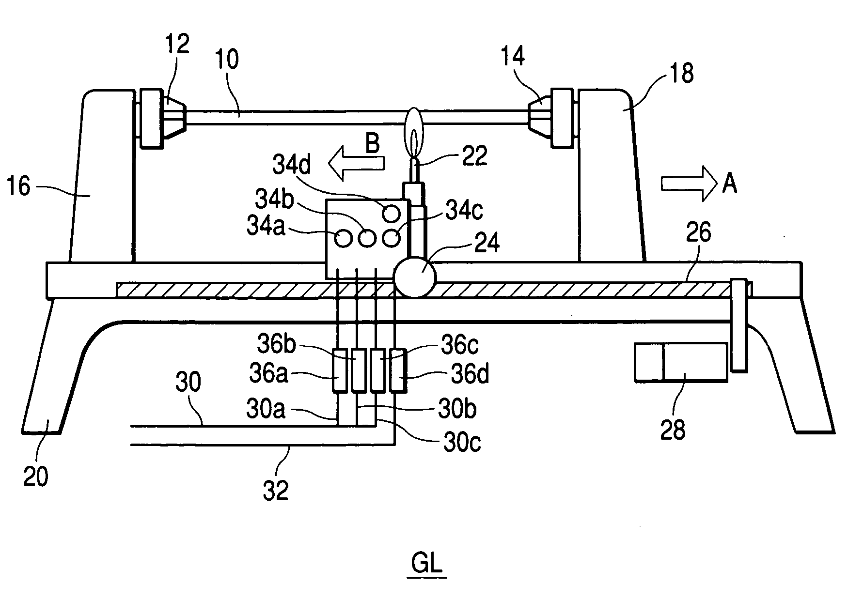
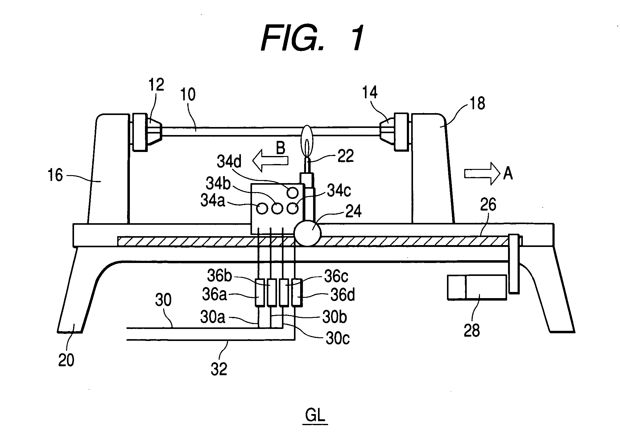
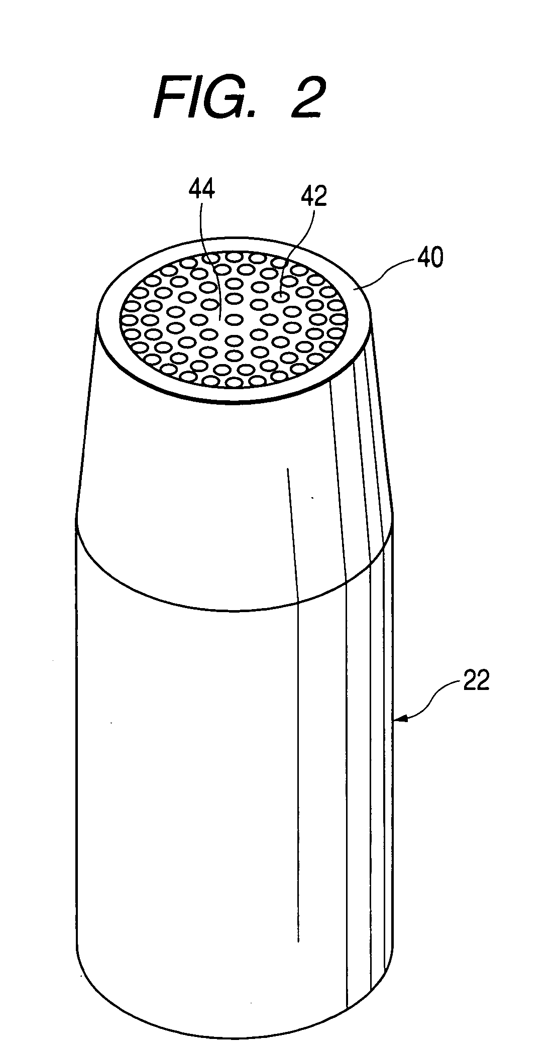
[0075] A burner of the type shown in FIG. 2 was set in a glass-working lathe shown in FIG. 1 and was used to drawing of a preform having a size of 60 mm.phi.. This burner had an outer hollow cylinder made of SUS 304 and having an inner diameter of 30 mm.phi. through which a hydrogen gas was passed. In the outer cylinder, fine pipes made of SUS 304 and each having an outer diameter of 3 mm.phi. and an inner diameter of 1.5 mm.phi. through which an oxygen gas was passed were arranged concentrically while grouping the fine pipes into three from inside toward outside. The groups of the fine pipes in the respective sections were, respectively, connected to different oxygen gas feed pipes. Thus, one hydrogen gas feed pipe and three oxygen gas feed pipes were provided wherein each feed pipe had a manual valve and MFC connected in series. By controlling the respective MFC's based on signals from a control unit, the movements of the burner and a tailstock and also the amounts of the gases fr...


PUM

PropertyMeasurementUnit
Lengthaaaaaaaaaa
Lengthaaaaaaaaaa
Lengthaaaaaaaaaa

Abstract

A method for processing a preform supported with a stationary chuck and a movable chuck of a glass-working lathe comprises providing a burner of a type which is able to create flame-controlled conditions by controlling flow rates of a flammable gas and a supporting gas wherein the supporting gas is discharged from at least one group of discharge pipes co-axially classified into plural groups that are, respectively, controllable with respect to a gas flow rate. The preform is processed under the flame-controlled conditions. A burner system and a preform processing apparatus comprising the burner system, both suited for realizing the method, are also described.

Description

[0001] 1. Field of the Invention[0002] This invention relates to processing of a preform for optical fiber, and more particularly, to a method for processing an optical fiber preform by use of a specific type of burner system and to an apparatus suited to carry out the processing method. The invention also relates to a burner system which is adapted for use in the method and apparatus mentioned above.[0003] 2. Related Art[0004] For the manufacture of optical or lightguide fibers, a porous glass matrix is initially made by deposition of fine particles of glass by a vapor-phase axial deposition (VAD) technique, an outside vapor deposition technique (OVD) or the like. The glass matrix is dehydrated and sintered or consolidated to obtain a clear vitrified mother ingot. This ingot is then roughly drawn, in an electric furnace, into a primary processed product called preform whose diameter is reduced to an extent as adapted for use in fiber drawing.[0005] The preform obtained in this mann...

Claims


Application Information

Patent Timeline
IPC IPC(8): C03B23/043C03B23/207C03B29/02C03B37/012F23D14/22F23D14/32F23D14/58
CPCC03B23/043C03B23/207C03B29/02C03B37/01205C03B37/01237C03B37/0124Y02E20/344F23C2900/9901F23D14/22F23D14/32F23D14/58F23D2900/00012C03B37/01257Y02P40/57C03B37/012
Inventor SHIMIZU, YOSHIAKI
Owner SHIN ETSU CHEM IND CO LTD
Learn More