Formation testing and sampling apparatus and methods

a technology of formation testing and sampling apparatus, applied in the field of underground formation investigation, can solve the problems of affecting the application of certain reservoir conditions, erroneous high estimate of reservoir producibility, and miss such a rich hydrocarbon deposit, etc., and achieves rapid withdrawal, increase the flow area, and fast measurement cycle

Inactive Publication Date: 2004-09-09
HALLIBURTON ENERGY SERVICES INC
View PDF15 Cites 85 Cited by
  • Summary
  • Abstract
  • Description
  • Claims
  • Application Information

AI Technical Summary

Benefits of technology

0013] In accordance with the present invention, deficiencies associated with the prior art are overcome using a novel approach, which is to increase the flow area of a pad-type device by using elongated sealing pads, capable of sealing off and collecting fluids from elongated portions along the surface of a borehole. Unlike prior art straddle packers, the sealing pads of a device made in accordance with the present invention can be deployed and withdrawn quickly for fast m...

Problems solved by technology

Thus, a formation testing tool, which has two probes located several inches apart along the longitudinal axis of the tool with fluid inlets being only a couple of centimeters in diameter, may easily miss such a rich hydrocarbon deposit.
On the other hand, in a vugular formation a probe may encounter an oil vug and predict high volume of hydrocarbon, but due to the lack of connectivity between vugs such high estimate of the reservoir's producibility will be erroneous.
Although the use of straddle packers may significantly improve the flow rate over single or dual-probe assemblies because fluid is being collected from the entire isolated area, it also has several important limitations that adversely affect its application in certain reservoir conditions.
Since the diameter of a typical formation-testing tool ranges from 10 cm to 15 cm and an inflated packer can increase this range approximately by an additional 10 cm, the packers may not provide sufficient isolation of the sampled zone.
As a result, sufficient pressure may not be established in the zone of interest to draw fluids from the formation, and d...

Method used


Image

  • Formation testing and sampling apparatus and methods
  • Formation testing and sampling apparatus and methods
  • Formation testing and sampling apparatus and methods

Examples


first embodiment

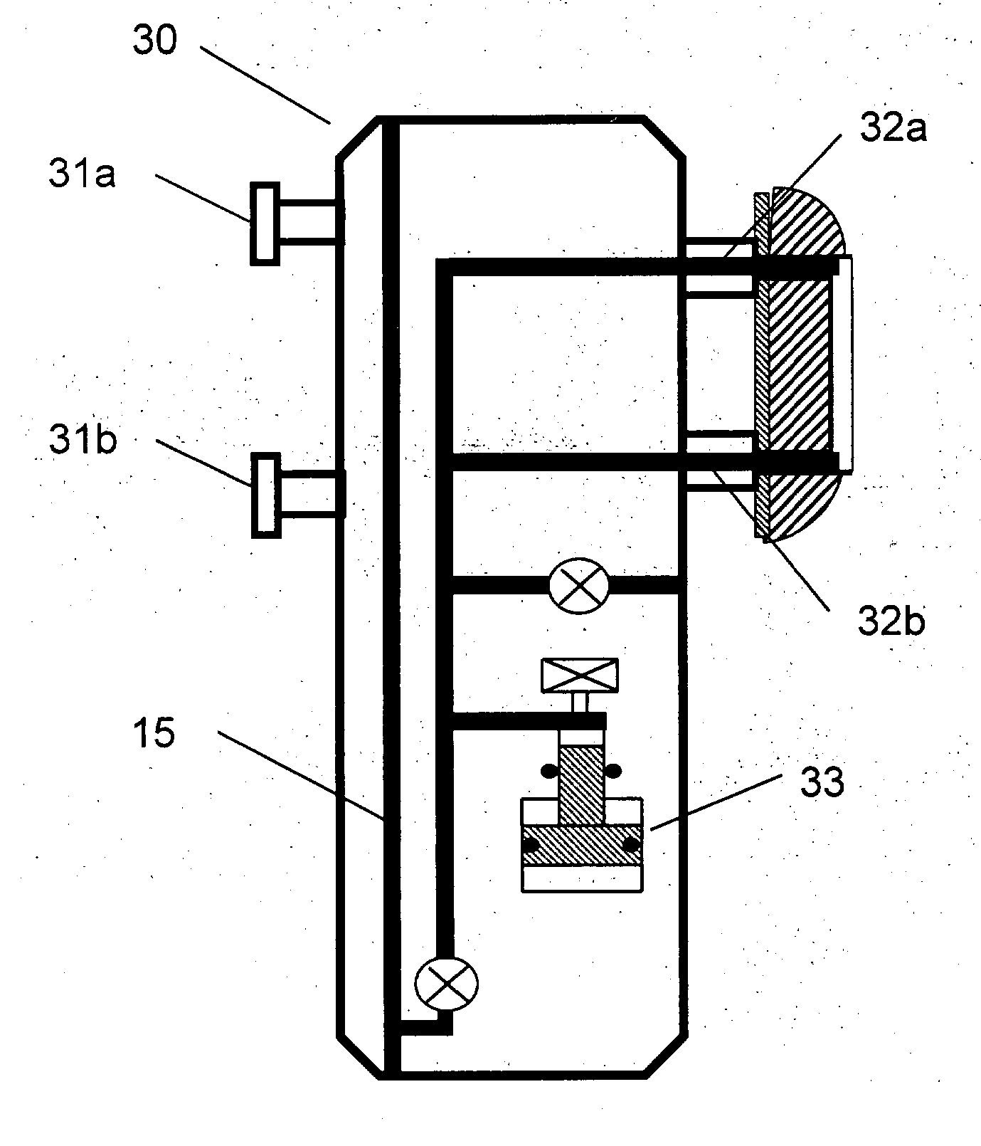
[0073] In a first embodiment, the identification of the laminate structure best suitable for testing, using the device and methods of this invention, is done by running the identifying logging tool first and then rapidly positioning the probes of the fluid tester in a sealing engagement with a surface of the borehole located by the logging tool. In the alternative, the fluid tester may be used in the same run as the logging device, to use the rapid-deployment ability of the Oval Pad design of the invention.

[0074] Advantages of the Proposed Approach

[0075] Some of the primary advantages to the novel design approach using elongated pads are as follows:

[0076] 1. enables placement of an isolated flow path across an extended formation face along the borehole trajectory;

[0077] 2. provides the ability to expose a larger portion of the formation face to pressure measurements and sample extraction;

[0078] 3. potential benefits in laminated sequences of sand / silt / shale, where point-source probe...


PUM


Abstract

Systems and methods for downhole formation testing. The invention is based on the use of one or more elongated sealing pads capable of sealing off and collecting or injecting fluids from elongated portions along the surface of a borehole. The, modified probe pads of a device-made in accordance with the invention increase the flow area by collecting fluids from an extended portion along the surface of a borehole, which is likely to straddle one or more layers in laminated or fractured formations. A tester device using the elongated sealing pads is capable of fast deployment and withdrawal to speed up the measurement cycles. Various designs and arrangements for use with a fluid tester, which may be part of a modular fluid tool, are disclosed in accordance with different embodiments.

Description

I. FIELD OF THE INVENTION[0001] The present invention pertains generally to investigations of underground formations and more particularly to systems and methods for formation testing and fluid sampling within a borehole.II. BACKGROUND OF THE INVENTION[0002] The oil and gas industry typically conducts comprehensive evaluation of underground hydrocarbon reservoirs prior to their development. Formation evaluation procedures generally involve collection of formation fluid samples for analysis of their hydrocarbon content, estimation of the formation permeability and directional uniformity, determination of the formation fluid pressure, and many others. Measurements of such parameters of the geological formation are typically performed using many devices including downhole formation testing tools.[0003] Recent formation testing tools generally comprise an elongated tubular body divided into several modules serving predetermined functions. A typical tool may have a hydraulic power module...

Claims


Application Information

Patent Timeline
IPC IPC(8): E21B49/10
CPCE21B49/10
Inventor FOX, PHILIP EDMUNDSHADE, MICHAEL E.GILBERT, GREGORY N.PROETT, MARK A.
Owner HALLIBURTON ENERGY SERVICES INC
Why Eureka
Try Eureka