Display control device

a control device and display technology, applied in the field of display control devices, can solve the problems of preventing the radiation of emi noise from the cable, affecting the design of the pc, and affecting the effect of the transfer clock signal,

Inactive Publication Date: 2004-10-07
FUJITSU LTD
View PDF7 Cites 78 Cited by
  • Summary
  • Abstract
  • Description
  • Claims
  • Application Information

AI Technical Summary

Problems solved by technology

(1) If the basic clock signal is the SSC signal, a jitter held on the SSC signal brings about a fluctuation of transfer timing, resulting in an occurrence of a problem of causing a distortion and a flicker on a display screen of the CRT that is analogously operated (which executes a time-division transfer and a display process).
In particular, the transfer clock signal becomes a large factor for causing the EMI noises.
Thus, the cable is in a position irresistible against electromagnetic radiation, and therefore a PC designer has a large problem of how the radiation of the EMI noises from the cable can be restrained.

Method used


Image

  • Display control device
  • Display control device
  • Display control device

Examples


first embodiment

[0037] [First Embodiment]

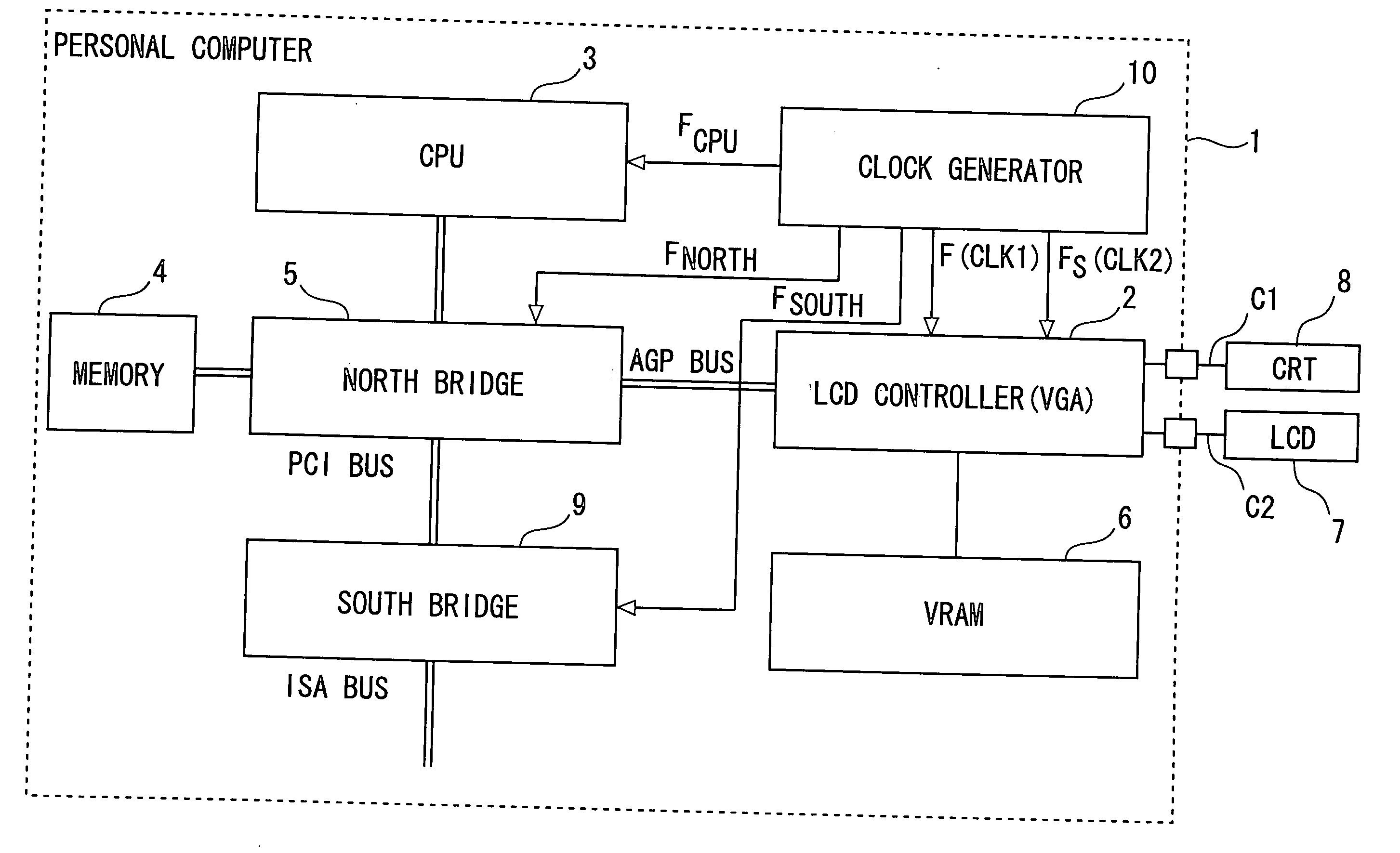
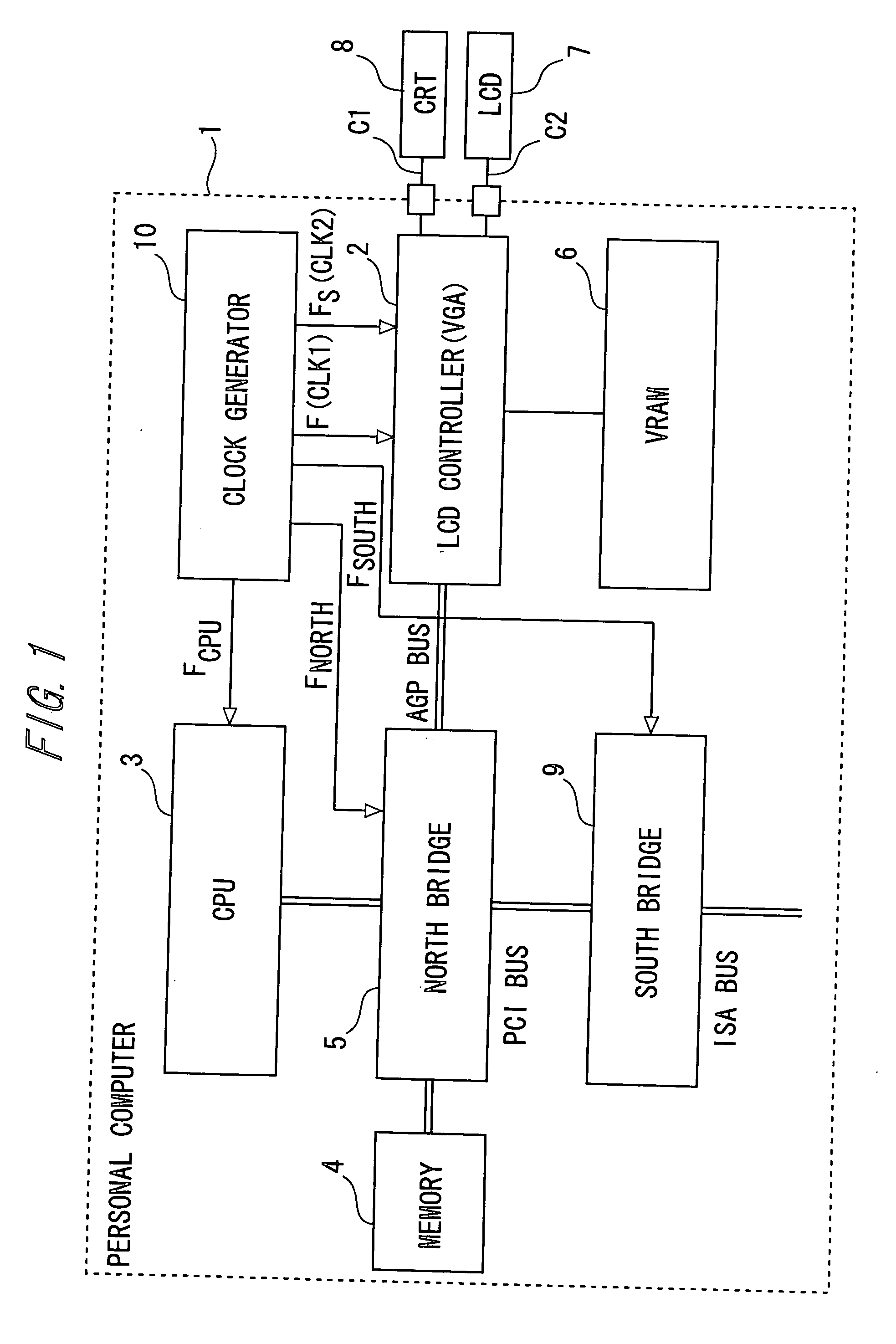
[0038] FIG. 1 is a diagram showing an outline of architecture of a personal computer (PC) 1 into which a display control device according to an embodiment of the present invention is installed. FIG. 1 illustrates architecture of a PC-AT compatible PC (AT compatible PC) by way an example, wherein a LCD controller 2 is illustrated as a display control device. The LCD controller can be exemplified by, for instance, VGA (Video Graphics Array).

[0039] The LCD controller 2 is connected via an AGP (Accelerated Graphics Port) bus to a north bridge 5 as a bridge circuit for controlling a CPU 3 and a memory (main memory) 4. Further, the LCD controller 2 is connected also to a video memory (VRAM (Video Random Access Memory)) 6 for storing data for displaying, and is connectable via cables C1 and C2 to a LCD display 7 and a CRT display 8 that display the display data stored on the VRAM 6.

[0040] The north bridge 5 is connected to a south bridge 9 via a PCI (Peripheral Com...

second embodiment

[0060] [Second Embodiment]

[0061] The LCD controller 2 shown in FIG. 4 executes the readout control of the video data from the VRAM 26 simultaneously in the CRT control unit and the LCD control unit. Therefore, in the case of simultaneously displaying the same picture (screen) on the LCD display 7 and the CRT display 8, a frame frequency of the LCD display 7 must be in principle the same as a frame frequency of the CRT display 8.

[0062] On the other hand, unless the frame frequency of the LCD display 7 is set equal to or slightly higher than a back light frequency (normally 60 Hz) (which is set equal to or higher than 70 Hz on the basis of 60 Hz), interference fringes due to the back light appear on the screen, with the result that a flicker on the screen is visible to the naked eye. Moreover, the LCD display 7 has a tendency that a time of after-image per frame decreases. Hence, if the frame frequency is the same as that of the CRT display 8, there is a possibility in which the flick...

third embodiment

[0069] [Third Embodiment]

[0070] FIG. 6 is a block diagram showing a LCD controller 2B by way of a third embodiment of the present invention. In FIG. 6, the timing generator 28B functions as a monitoring means for monitoring a data quantity (data-transfer quantity) per unit time of transfer to the LCD display 7 in a way that monitors a resolution of the video data and the number of colors, which are written to the VRAM 26, and inputting a signal indicating the data quantity (a data quantity signal) to a spread spectrum IC 10B.

[0071] The data quantity of the monitoring object is divided (classified) into a plurality of levels (classes), wherein threshold values are provided between the respective levels. The timing generator 28B outputs, as a data quantity signal, a bit or bits indicating a level of the data quantity. For instance, in the case of dividing the data quantity into four levels, the data quantity signal is expressed in 2 bits. The timing generator 28B changes the bit value...


PUM


Abstract

A display control device comprises: a cathode ray tube (CRT) control unit for transferring, to a CRT display, a CRT transfer clock signal, a video data signal and a synchronous signal in accordance with the CRT transfer clock signal generated from a first clock signal having a constant and stable cycle; and a liquid crystal display (LCD) control unit for transferring, to a LCD display, a LCD transfer clock signal, a video data signal and a synchronous signal in accordance with the LCD transfer clock signal generated from a second clock signal as a spread spectrum clocking signal generated based on the first clock signal.

Description

[0001] 1. Field of the Invention[0002] The present invention relates to a display control device for transferring video data to a CRT (Cathode Ray Tube) display and a LCD (Liquid Crystal Display) display.[0003] 2. Description of the Related Art[0004] In the field of general-purpose computers such as a personal computer (PC), an office computer, etc., there has hitherto been a notebook-type PC displaying pictures or images on a LCD display by use of a display control device (a LCD controller) being built-in a LCD interface and a personal computer / office computer that is digitally connected to the LCD display.[0005] As a recent tendency, there have increased cases of supplying a market with, as main commercial articles, the notebook type PC using the LCD display and the desktop type PC that is adopted the LCD as standard equipment. Further, by reduction of prices of the PCs, a domestic-utility-rate (percentage) of the PCs rises year after year.[0006] The standard of VCCI (Voluntary Co...

Claims


Application Information

Patent Timeline
Patent Type & Authority Applications(United States)
IPC IPC(8): G06F3/14G09G5/18G09G5/395
CPCG06F3/1431G09G5/18G09G5/395G09G2330/06
Inventor SHIMIZU, HIROTOSHI
Owner FUJITSU LTD
Why Eureka
Try Eureka