Light emitting element and light emitting display

a technology of light emitting elements and light emitting displays, which is applied in the direction of power-operated mechanisms, door/window fittings, wing accessories, etc., can solve the problems of significant reduction in the efficiency of emitted light use, reduced display quality, and reduced visibility of displayed images

Inactive Publication Date: 2004-10-21
SANYO ELECTRIC CO LTD
View PDF4 Cites 45 Cited by
  • Summary
  • Abstract
  • Description
  • Claims
  • Application Information

AI Technical Summary

Problems solved by technology

The reflection of ambient light becomes a major cause of contrast reduction especially when the display displays black, and, in addition, because a surrounding image may be projected onto the viewing surface (reflective surface) of the metal electrode, reduction in visibility of a displayed image may occur, thus causing reduction in display quality.
Thus, the efficiency of use of

Method used


Image

  • Light emitting element and light emitting display
  • Light emitting element and light emitting display
  • Light emitting element and light emitting display

Examples


Embodiment Construction

[0030] A preferred embodiment (hereinafter, referred to as an "embodiment") of the present invention will be described with reference to the drawings.

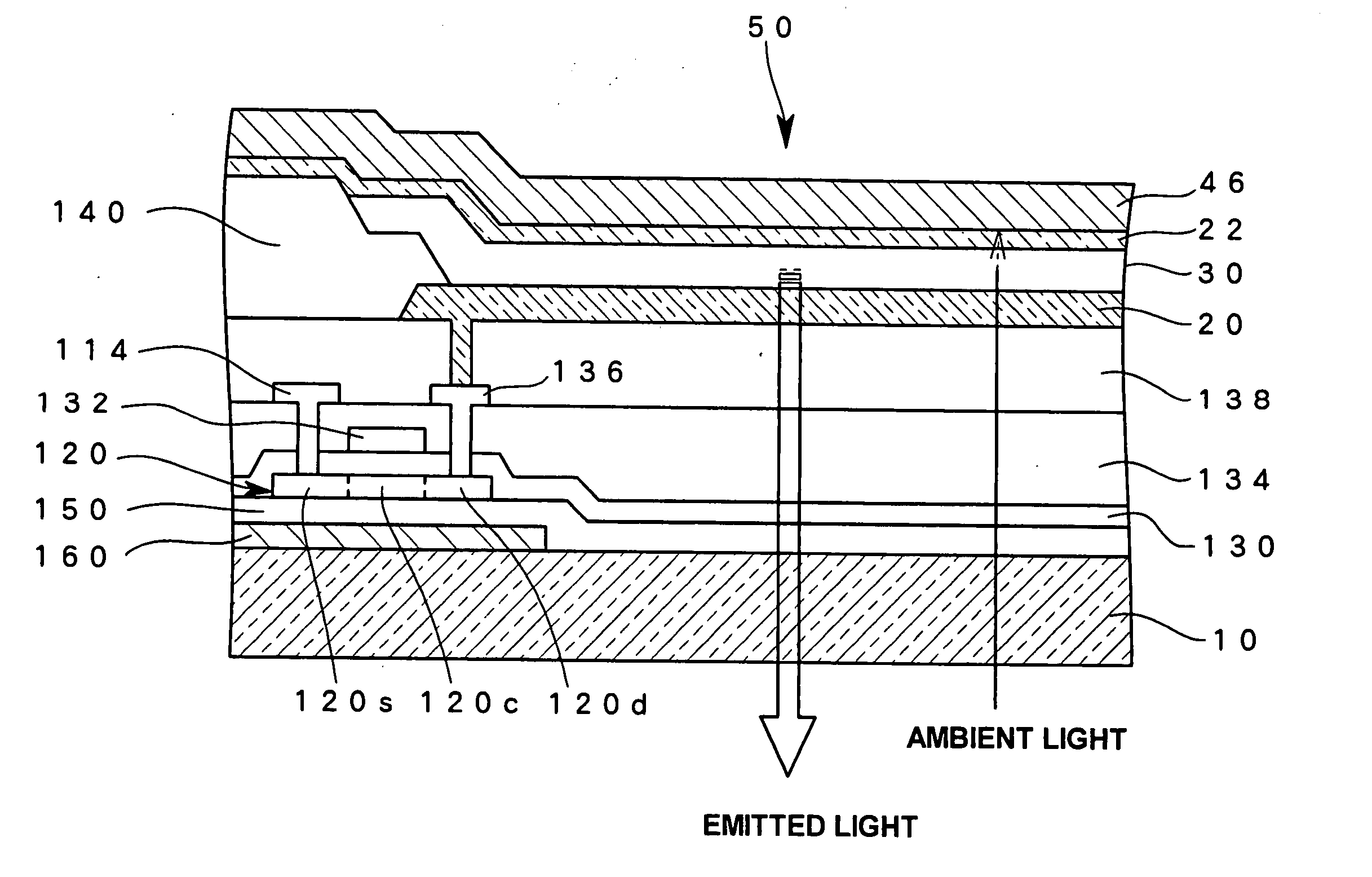
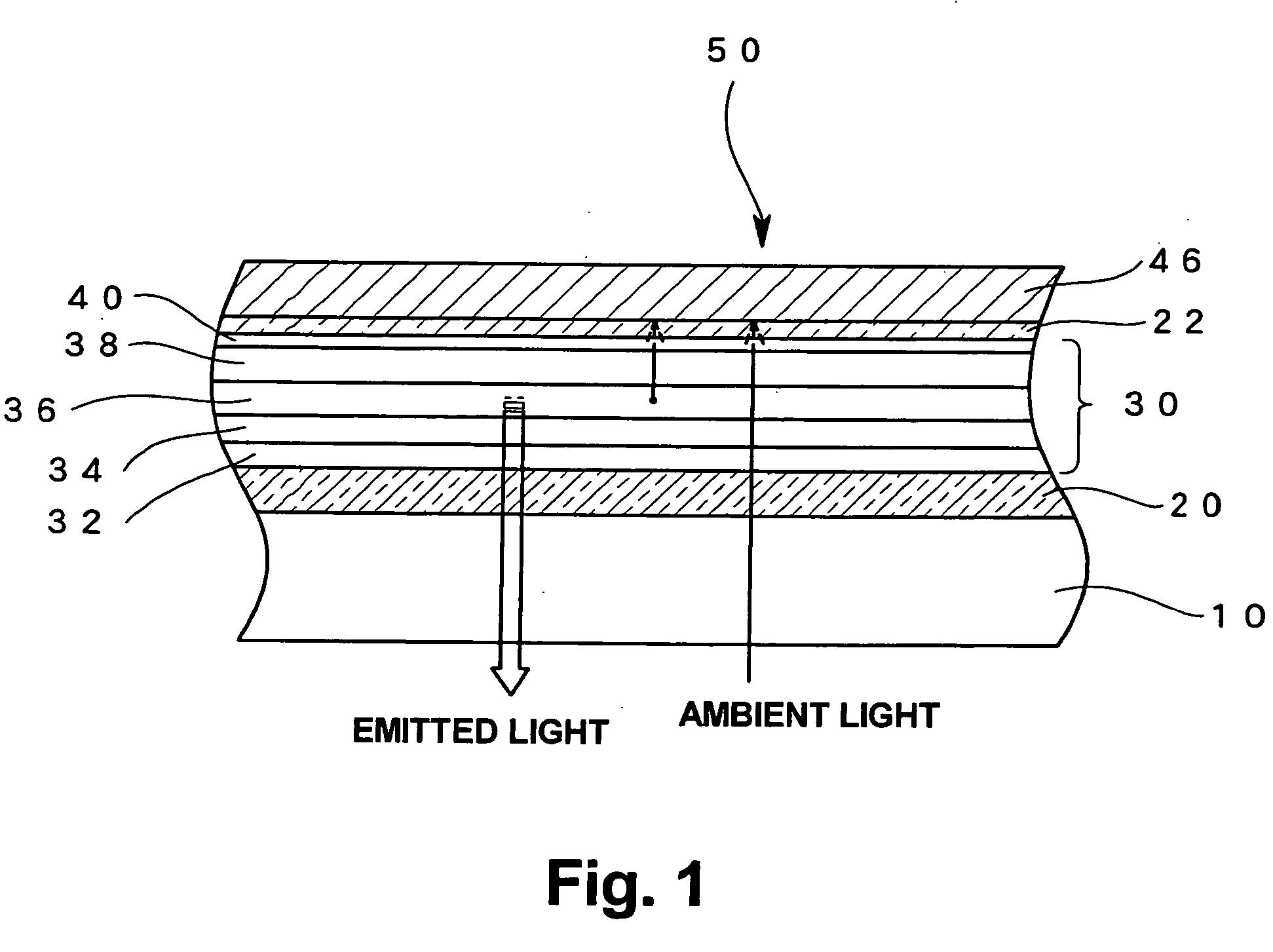
[0031] An EL element is suitable as an example light emitting element according to the embodiment of the present invention. Using such an EL element as an illustrative example, FIG. 1 shows a schematic cross section of an element according to this embodiment of the present invention. A transparent substrate made of glass, plastic, or the like is used as a substrate 10, and components of an EL element are layered over the transparent substrate 10. In this example, an EL element 50 is an organic EL element which uses an organic compound as a light emitting material, and a light emitting element layer 30 containing the organic compound is formed between a first electrode 20 and a second electrode 22.

[0032] In the organic EL element 50 as shown in FIG. 1, the first electrode 20 is made of a transparent electrically conductive material such...


PUM


Abstract

A light emitting element such as an organic EL element comprises a first electrode formed of a transparent electrode on a side from which light is emitted to outside, and a second electrode formed on a back side of the element so as to be opposed to the first electrode with a light emitting element layer interposed therebetween. The second electrode is designed to be a semitransparent electrode, and, on a further back side of the second electrode, an antireflective layer with a low optical reflectivity is formed. The semitransparent second electrode does not reflect but transmits light incident from outside of the element and transmitted through the transparent electrode, and then the antireflective layer absorbs the transmitted light, thereby making it possible to suppress reflection of ambient light on a surface of the back-side electrode and to achieve improvement in contrast. The second electrode may, for example, be made of a metal material formed as a thin film, or be provided with apertures to thereby exhibit semitransparency.

Description

[0001] 1. Field of the Invention[0002] The present invention relates to a structure of a light emitting element as used in a display or the like, and in particular to a structure on the back side of a light emitting element.[0003] 2. Description of the Related Art[0004] Recently, a great deal of attention has come to be focused on electroluminescence (hereinafter, referred to as EL) elements as light emitting elements, and research is being conducted on displays which use such EL elements. This research is directed at, for example, creating substitutes for displays such as liquid crystal displays (LCDS) or CRTs.[0005] Among various types of EL element, an organic EL element which uses an organic compound as a light emitting material has a structure wherein a light emitting element layer containing organic light emitting molecules is interposed between a hole injection electrode (anode) and an electron injection electrode (cathode). More specifically, a transparent electrically condu...

Claims


Application Information

Patent Timeline
IPC IPC(8): H05B33/02H01L27/32H01L29/04H01L51/50H01L51/52H05B33/14H05B33/22H05B33/28
CPCH01L27/3244H01L51/5284H01L51/5203H10K59/12H10K50/865H10K59/805E05F15/73E05F15/632E05D15/063E05Y2900/132E05Y2201/688E05Y2201/684H10K50/805
Inventor NISHIKAWA, RYUJI
Owner SANYO ELECTRIC CO LTD
Why Eureka
Try Eureka