Electromechanical linear drive

a linear drive and electromechanical technology, applied in mechanical energy handling, mechanical equipment, mechanical energy handling, etc., can solve the problems of not supporting normal load, complex design, and inability to normal support any load,

Inactive Publication Date: 2004-11-11
SUMITOMO SHI DEMAG PLASTICS MACHINERY
View PDF7 Cites 38 Cited by
  • Summary
  • Abstract
  • Description
  • Claims
  • Application Information

AI Technical Summary

Problems solved by technology

A problem associated with motors of this type is how to support the hollow-shaft rotor so that it remains exactly centered, since even relatively small deflections of the rotor can cause it to contact the stator, which can lead to thermal or mechanical destruction of the motor.
This

Method used


Image

  • Electromechanical linear drive
  • Electromechanical linear drive
  • Electromechanical linear drive

Examples


Embodiment Construction

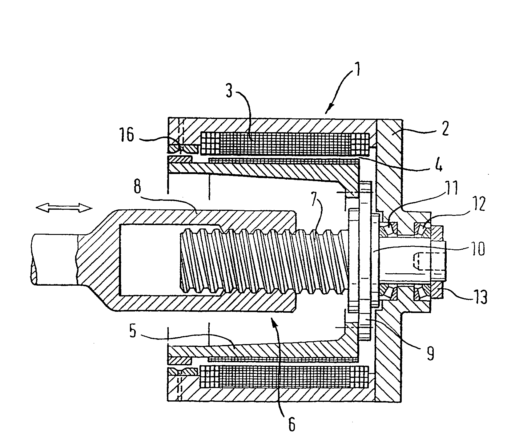
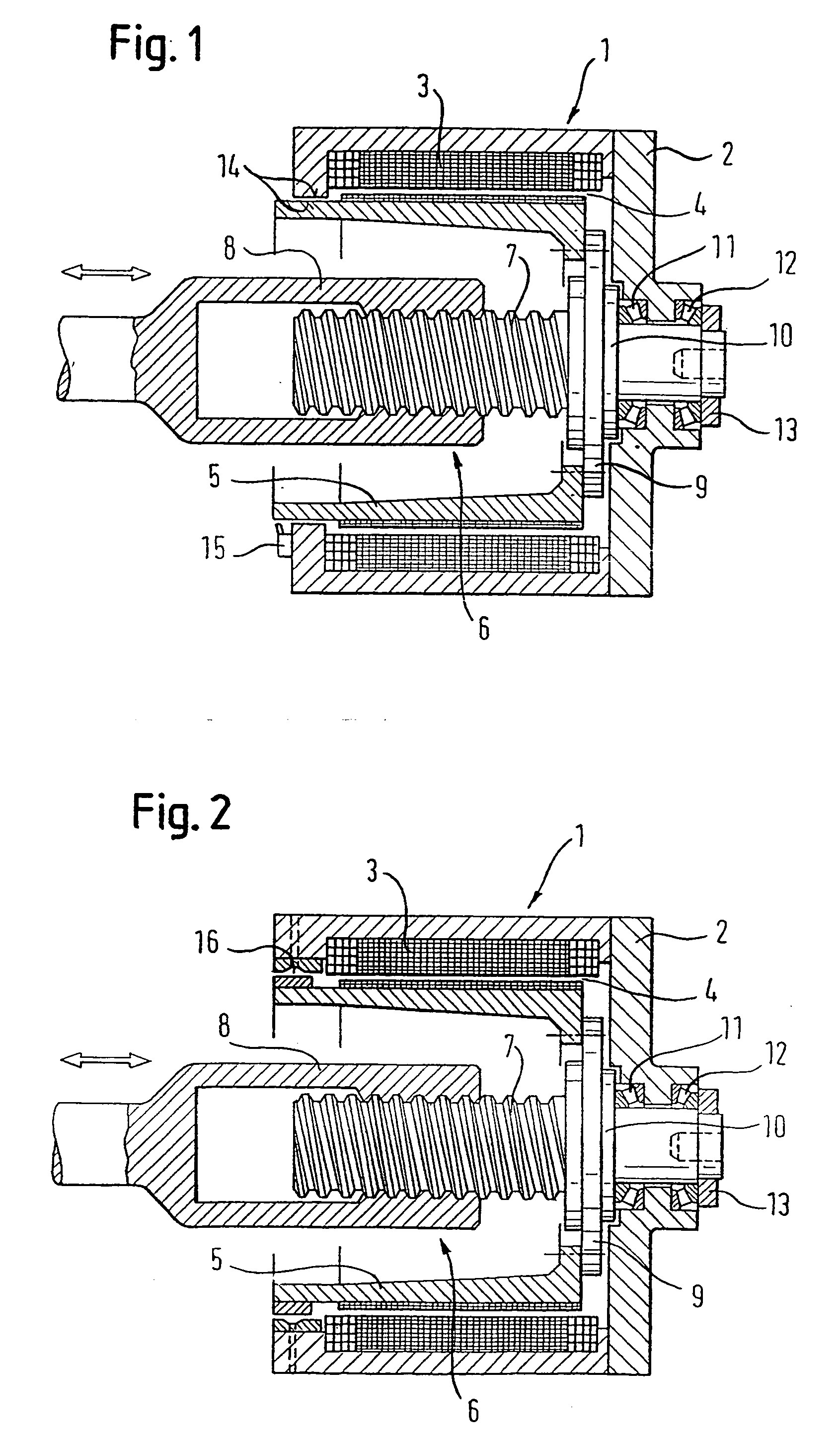
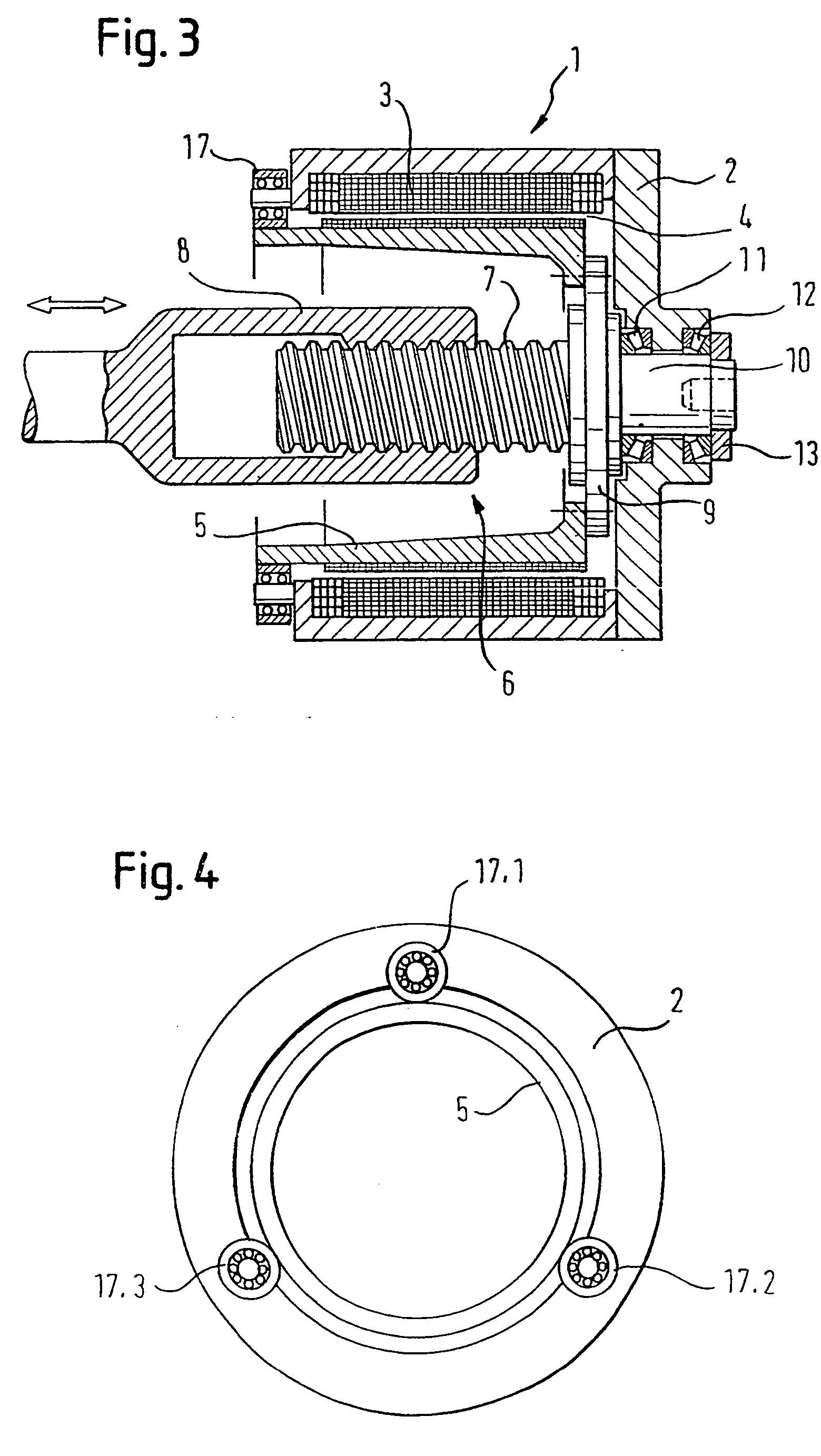
[0019] The electromechanical linear drive shown in FIG. 1 contains as its main components an electric rotary motor 1, which consists of a stator 3, mounted in the motor housing 2, and a large-diameter hollow-shaft rotor 5, magnetically coupled to the stator across a narrow air gap 4. The motor drives a spindle gear, designated overall by the reference number 6, which is housed inside the hollow-shaft rotor 5 and consists of a spindle shaft 7, which is connected nonrotatably to the rotor 5, with which it is coaxial, and a sleeve-like spindle nut 8, which is helically threaded to engage with the spindle shaft 7. The spindle nut, which is prevented from rotating, thus converts the rotational movement of the spindle shaft 7 into axial movement and thus controls the reciprocating motion of the plasticizing screw (not shown) of an injection molding machine.

[0020] At its end closed by the end wall 9, the hollow-shaft rotor 5 is provided with a bearing journal 10 of reduced diameter, which ...


PUM

PropertyMeasurementUnit
Forceaaaaaaaaaa
Distanceaaaaaaaaaa

Abstract

The invention relates to an electromechanical linear drive, in particular for an injection moulding machine, comprising an electric motor with a hollow-shaft rotor, open on one side, with a subsequent screw gear which converts the rotational movement of the hollow-shaft rotor into a linear movement. The hollow-shaft rotor is supported on the motor housing, at the end thereof closed by a end wall, such as to rotate, by means of a central bearing spigot projecting axially from the end wall. According to the invention, an extremely stable-running, exactly central and fail-safe rotor bearing may be achieved with a simple construction and in an economical manner, whereby the bearing spigot is supported on the motor housing such as to rotate by means of at least two axially pre-tensioned, counter-rotating, individual bearings, separated in the longitudinal direction and supporting longitudinal and transverse forces and, in the region of the open rotor end, an emergency running safety device for an eccentric rotor displacement is provided.

Description

PRIORITY CLAIM[0001] This application claims priority under 35 U.S.C. .sctn.120 from PCT International Application No. PCT / EP02 / 08361, filed Jul. 26, 2002, and designating the United States.[0002] 1. Field of the Invention[0003] The invention concerns an electromechanical linear drive, especially for an injection molding machine, the drive having a motor housing containing a stator, a hollow cylindrical rotor received in the housing to form an electric motor having a magnet gap between the stator and the rotor, and a helical gear connected to the rotor for converting rotational movement of the rotor to linear movement.[0004] 2. Description of the Related Art[0005] Electric motors for producing high torques, such as those described, for example, in DE 32 13 172 C2, as high-torque motors, have a hollow-shaft rotor of large diameter, which is usually open at one end and which, together with the stator, bounds a narrow magnet gap with a circumferential length that corresponds in size to...

Claims


Application Information

Patent Timeline
IPC IPC(8): B29C45/50B29C45/84F16C19/52H02K5/173H02K7/06H02K7/08
CPCB29C45/5008B29C45/84B29C2045/5028H02K5/1735H02K7/06Y10T74/18056H02K7/088F16C39/02F16C19/507F16C21/00H02K7/085
Inventor ICKINGER, GEORG
Owner SUMITOMO SHI DEMAG PLASTICS MACHINERY
Why Eureka
Try Eureka